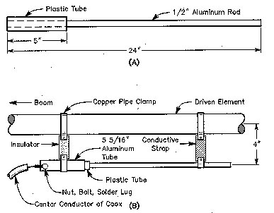
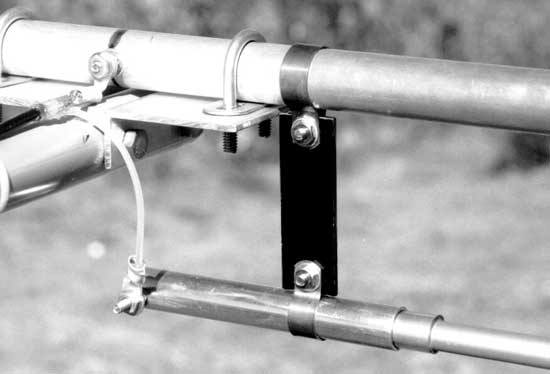
Clearly capacitance is the key
Capacitance is just one part of it. The gamma match in your question is three things:
- A sort of folded dipole, performing an impedance step-up
- A parallel shorted transmission line stub, adding shunt inductance
- A series capacitance
An equivalent circuit is:
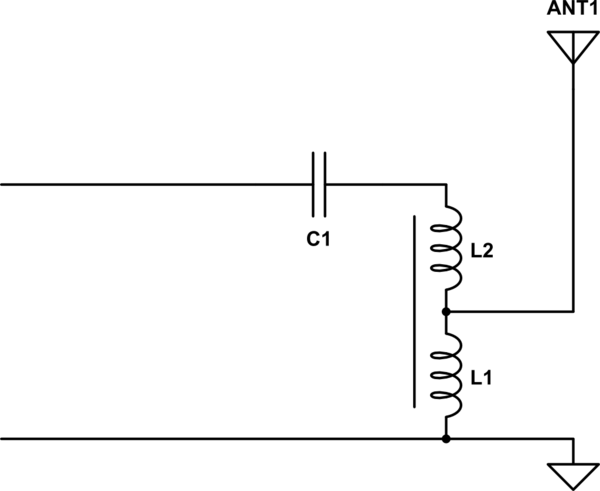
simulate this circuit – Schematic created using CircuitLab
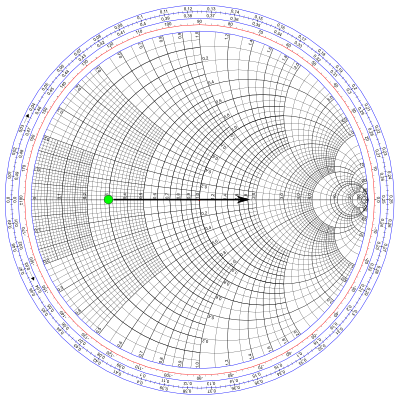
So let's say we have some antenna with a feedpoint impedance of $(15+j0)\Omega$. On a Smith chart, we have this:
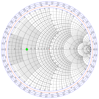
Our goal is to move that dot to the middle of the circle. How does a gamma match accomplish that?
sort of a folded dipole
The first point is probably the hardest to understand. Consider that in a folded dipole, the impedance is four times that of an ordinary dipole because the antenna current flows in both legs of the dipole, but only half of it in the leg where the feedpoint is. Since current is halved while radiation resistance remains essentially unchanged, impedance is quadrupled.
Now consider the gamma match: the same condition exists. Some of the current flows through the main antenna element, and some of it through the gamma bar, and this provides the same sort of impedance step-up. In fact, if you move the shorting strap all the way to the end of the antenna, it's exactly a folded dipole.
Typically, the gamma match is constructed to give an even more than 4:1 impedance step-up. By making the gamma bar smaller than the main element, the gamma bar will take an even smaller share of the total current. Even less current means a higher impedance transformation.
In terms of the equivalent circuit, the size of the gamma bar influences where the autotransformer formed by L1 and L2 is tapped. Here's the effect on the Smith chart:
a parallel shorted transmission line
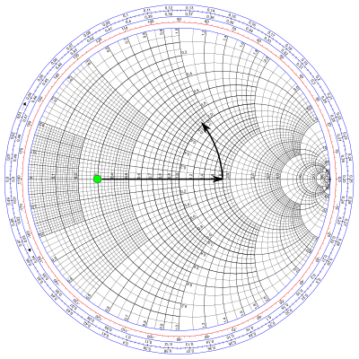
The gamma bar running parallel to the antenna element make a twin-lead transmission line. It's shorted stub, and less than $\lambda/4$ long, so it looks like an inductor. The position of the shorting bar determines the inductance, the value of L1+L2 in the equivalent circuit above.
If the shorting bar is moved all the way to the end of the antenna, then the susceptance is zero, and has no effect on the feedpoint impedance. As the shorting stub is moved closer to the feedpoint, it makes the susceptance larger, as if L1+L2 were becoming smaller inductors.
With parallel inductance added, our Smith chart looks like this:
a series capacitance
The capacitor is formed by the aluminium tube, with the gamma rod inside it, insulated by plastic. This is an optional feature of the gamma match, and it's not always present, or configured exactly this way. But with it, we can do this:
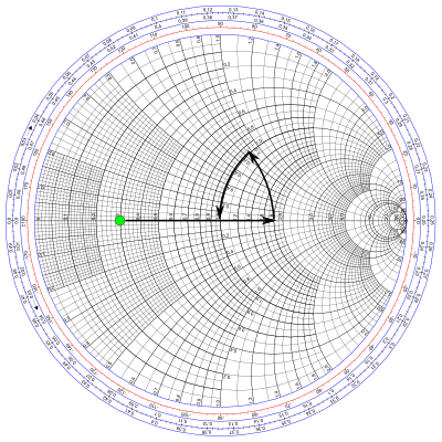
Mission accomplished.
As configured, C1 and L1+L2 form a step-down L network. It's also possible to trim the antenna to be a bit short, in which case it will provide some capacitance, but on the other side of the inductance. In this case, you get a step-up L network.
Since antenna can also be tuned to be exactly resonant (present a purely resistive feedpoint impedance), you don't technically need to add any inductance or capacitance: just the transformation from the first point is sufficient and you could have an ordinary a folded dipole. However this frequently isn't done in practice since adjustment of the impedance transformation requires changing the diameter of either the gamma bar or the antenna element, which is tricky.
It's also the case that the gamma match works somewhat as a balun. If it steps up the impedance seen looking in from the coax, by reciprocity it also steps down the impedance looking in the other direction back into the differential mode of the coax. The common-mode is left alone but is now a relatively higher impedance. So, it might be more desirable to step-up too much, then step-down with the L network. Even so, for an antenna with high directivity some additional common-mode suppression may be necessary: combined with the gamma match it may be even more effective. G8HQP provides a more complete explanation with all the math if you want more detail.
