2
$\begingroup$

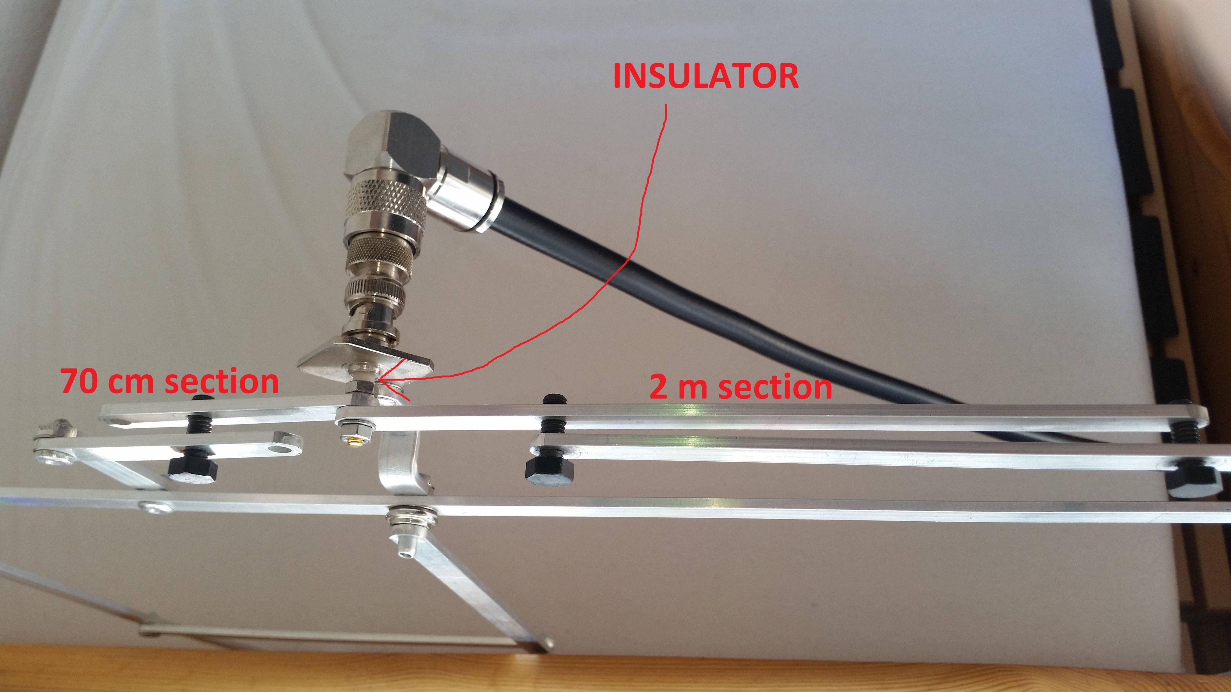
I've recently obtained a Quad Loop antenna for 2 m and 70 cm that's fed through gamma match, as shown in the picture:

Photo of gamma match section in YZ plane

The shorter metal bars are connected to the hot side of the BNC, while the longer assembly is connected to the ground of the BNC. Screws are made of dielectric material.

Here's a photo of the whole antenna:
Photo of the antenna in XY plane]

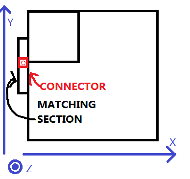
Here's drawing of the whole antenna. The connector and matching section is on top of the parallelogram part of the antenna and is on the left side.

Diagram of the antenna with matching section and connector shown in XY plane

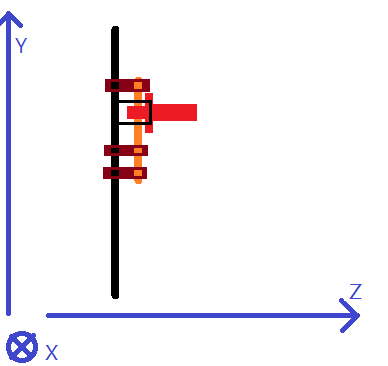
Diagram of the antenna with matching section and connector shown in YZ plane

On these (not to scale!)diagrams, the BNC connector in in red, the antenna assembly that connects to the connector's ground side is in black, the assembly that connects to the connector's hot side is in orange, the screws are in brown. The orange and black parts are not directly connected, it's just that I don't know how to draw good 3D shapes.

The instruction manual says that I'm supposed to adjust the distance between the two parts and then secure both parts with screws when correct distance has been determined.

So my question is: How do I adjust the distance using an SWR meter? More explicitly, how do I determine if I should increase or decrease the distance between the two components? Is there a rule of thumb, like the rule for short/long dipoles, for this case? How do I take into account two bands?

EDIT: Link to the manual was requested in comments, so here it is. Here's the manufacturer's webpage about the antenna, but it only provides specifications, such as mass, wind load, radiation angles and so on. Since the manual is on German only, here's a translation:

Assembly and adjustment

The attachment of the antenna is possible in all polarization modes on a smooth, non-conductive surface with the two suckers. The window pane offers the best HF position! A suspension at the corner (diamond shape) often brings good results. SWR setting: Unscrew the plastic isolator screws, change the plate spacing and turn the screw back in.

Description

The antenna is a full-wave loop (quad-loop), available as monoband antenna for 2m or 70cm, or as a duo antenna for both bands. The gain is about 1 dBD. The individual parts are connected via fatigue-free special joints. One of the connections is a metal push button so that the antenna can be very small. The SWR adjustment is easy to make with a plastic screw. The antennas are attached to the window pane with two oversized suckers; Depending on the suspension, operation is possible either with horizontal or with vertical polarization.

Photo of the connector:
Image of the center connector

There are 3 versions of the antenna that I have: 2 m version, 70 cm version and the dual-band version. The sections marked as 70 cm and 2 m on the image are the sections that appear on the mono-band versions of the antenna. They are connected to the center pin of the BNC connector. The big frame is connected to the ground of the BNC.

$\endgroup$
10
  • $\begingroup$ 1. I can't figure out exactly what your antenna design is from the picture and description is, and "quad loop" doesn't seem to be unambiguous. Could you add a picture of the antenna from another angle and mark on the diagram where the connector is? 2. Also, what advice are you looking for beyond the basic "move it, and if that increases SWR, move it in the other direction"? $\endgroup$
    – Kevin Reid AG6YO
    Commented Oct 1, 2015 at 22:10
  • $\begingroup$ @Kevin Reid AG6YO♦ 1: I hope I made the design a bit more clear with the two new diagrams. The two black squares are connected to the ground of the BNC and the signal side if connected to the orange section on the second diagram. 2. I'm looking for any advice more in-depth than what you mentioned. I mean, for dipoles, we can take a number of SWR measurements and then determine if the antenna is more inductive or capacitive. Is there something similar for this setup? $\endgroup$
    – AndrejaKo
    Commented Oct 1, 2015 at 22:38
  • 1
    $\begingroup$ That does help (though I think a non-edge-on photo of the antenna would also help). I don't myself have any advice for tuning gamma matches, sorry. $\endgroup$
    – Kevin Reid AG6YO
    Commented Oct 1, 2015 at 22:42
  • $\begingroup$ @Kevin Reid AG6YO♦ Thanks for comment anyway! I definitely should try to make the question a bit clearer. I'll try getting a sort-of useful photo of a non-edge side of the antenna. The biggest issue is that there's not much to take a photo of with this type of antenna. $\endgroup$
    – AndrejaKo
    Commented Oct 1, 2015 at 22:44
  • $\begingroup$ Is the instruction manual linkable? $\endgroup$ Commented Jun 15, 2017 at 0:35

1 Answer 1

2
$\begingroup$

Well, I'm a little out of my depth, but this does seem to have all the usual parts of a gamma match: the matching section hanging off the main loop is a balanced transmission line, and the part connected to the BNC center is spaced off it, so the coax is coupled capacitively into that transmission line.

There are two transmission lines, and two gamma matches, one to the left and one to the right, I'm guessing one for each band. Getting a match on both bands will probably require adjustment in little steps with frequent checks on each band since the tuning for one band will have some effect on the other.

There's some information on how gamma matches work generally: What is a Gamma match in the context of the driven element of a Yagi antenna?

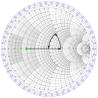
It appears the only adjustable thing here is the spacing of the capacitor. Most pictures of gamma matches use some arrangement with tubing to make a coaxial capacitor which slides for adjustment, but I don't see why this design wouldn't work the same way. Turning the screws to bring the pieces closer together increases the capacitance. That will move the feedpoint impedance along the path of the final arrow on this Smith chart: closer spacing -> higher capacitance -> longer arrow.

So, the idea would be if the feedpoint impedance is inductive, then turn the screws to bring the plates closer together. If it's capacitive, move them apart. You should be able to cancel out any reactance in the impedance. And if everything is right, you'll end up around 50Ω.

If all you have is an SWR meter, you are effectively measuring the distance from the center of that chart. In that case you don't have any information about which way you need to go, so you can just make small adjustments and see if it's getting better or worse. If the match is just terrible no matter what, it will be pretty hard to fix it except by trial and error. Might be a good excuse to build an impedance bridge :)

$\endgroup$

You must log in to answer this question.

Not the answer you're looking for? Browse other questions tagged .