2
$\begingroup$

Short question:

What are the advantages and disadvantages of using gamma (solid element) or beta (split element) matching a yagi?

Long question:

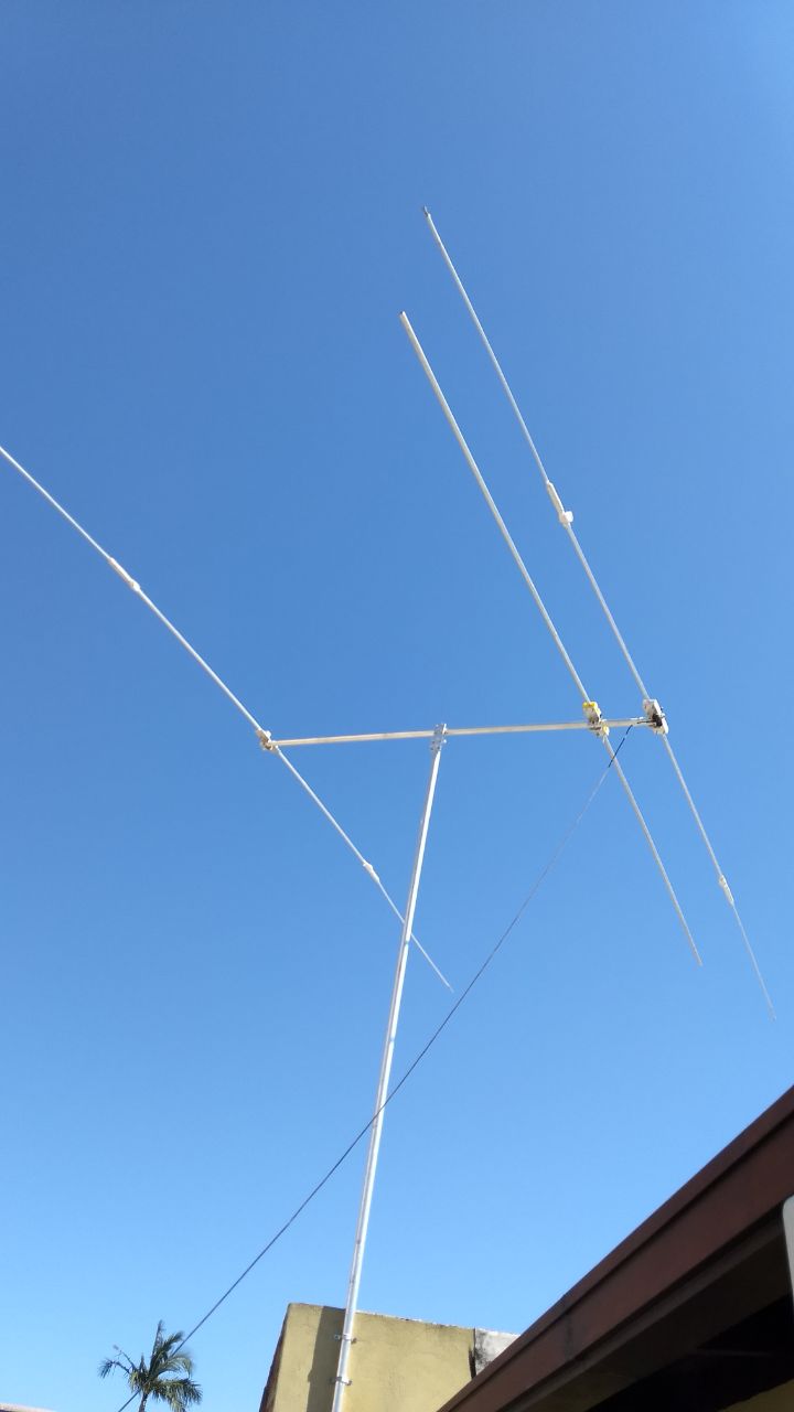
A while ago I built a coil loaded yagi for the 20M band, with a small coil in the middle, for a total element length of 6M (3M to each side). This element is split, center fed, like any traditional dipole.

Yesterday I added a second element, for the 10M band. I didn't have enough material to add a reflector, so basically I have a rotatable 10M dipole sharing the boom. The match was good enough, though, to provide a reasonable SWR of 1:1.5. It's a little too long, but I don't want to trim it until I add the reflector.

enter image description here

I understand that, when I add the reflector, the feedpoint impedance at resonance may drop. I've been considering the options for matching a low impedance to 50 ohms, which so far I've only done with simple LC networks.

From my understanding it comes down to:

  • Use a split element (like any traditional dipole), and match it, if necessary, with a "hairpin" or "beta" match
  • Use a solid element, and drive it with a "gamma" match

I couldn't find any information information, other than anecdotical "I would never do it this way", on the advantages and disadvantages of both types of matches. The great benefit from solid + gamma, is that it makes design of the antenna much easier and stronger, since you don't need to cut the tube in the center. But apparently the gamma match isn't as broadband as a hairpin (that's all anecdotical info I found on different forums).

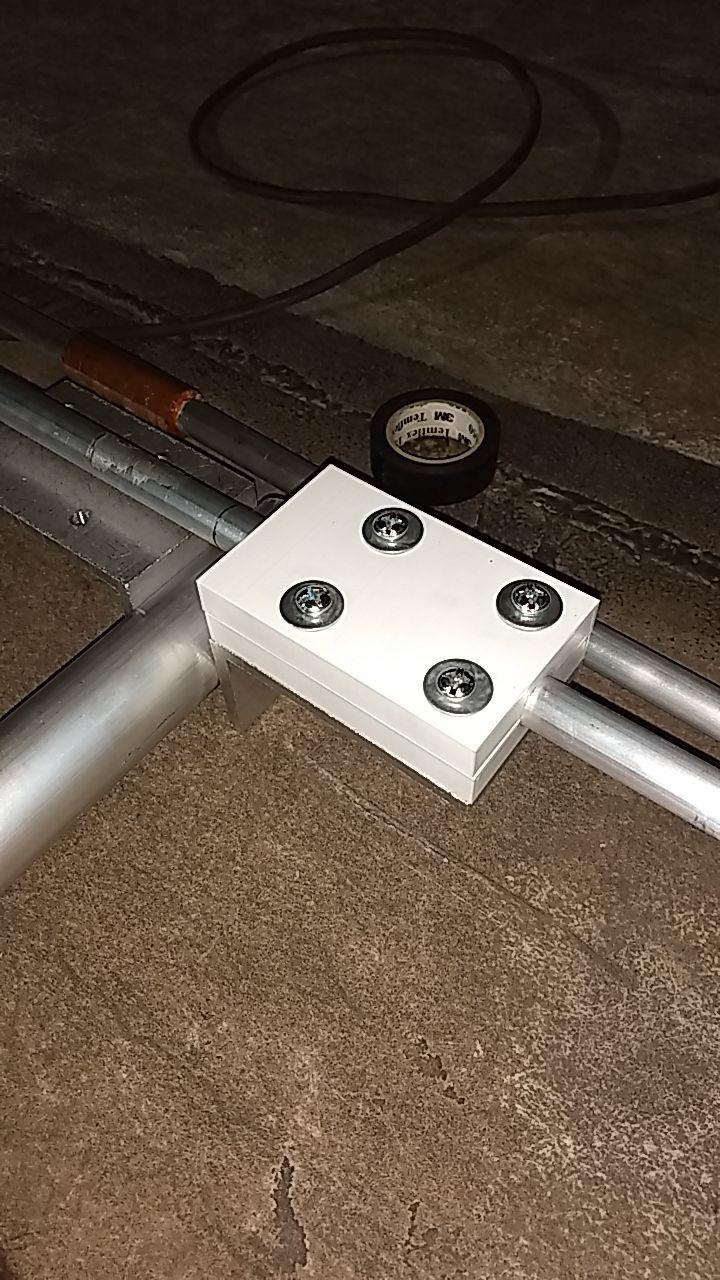
I solved the boom isolation by using strong L shaped alu pieces (6mm thick, 100mm flange length), and the element is sandwiched between two 3D printed insulators, bolted to this L (PETG is an amazing 3D print material). So I don't mind doing it this way if split elements have any significant advantage over a solid element.

enter image description here

Environmental factors to conside at my location are winds, which are not often but once or twice a year, very strong (250km/h gusts are not unheard of). I need to design the yagi so I can drop it to a safe parking location, but that's a different issue. There is no snow, ice, or freezing rain to worry about.
$\endgroup$
3
  • $\begingroup$ You might find your answer in one of these questions. $\endgroup$ Commented Apr 13, 2020 at 15:19
  • 1
    $\begingroup$ @MikeWaters yeah the closest I found was ham.stackexchange.com/questions/5797/… but it doesn't really discuss the differences between the match types. Though, opposed to what other info I found in other places, it says that the gamma gives a wide match, and hairpin is similar... sigh. $\endgroup$
    – hjf
    Commented Apr 13, 2020 at 15:31
  • $\begingroup$ It looks like you are feeding your split driven element with coax. It's not clear from the photo whether you are using a balun. Can you please edit your question and clarify this? $\endgroup$ Commented Apr 13, 2020 at 17:33

2 Answers 2

3
$\begingroup$

I'd say you're overthinking it. Mechanical issues, like ease of construction and strength are the biggest differences. Different matching arrangements may yield more or less flexibility in adjustment.

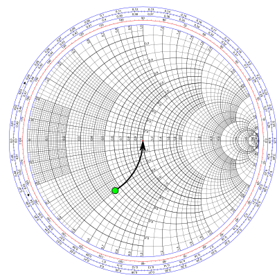
The hairpin match is simply a parallel inductance. The idea is to make the driven element a bit short so it presents a capacitive impedance, then that inductance cancels it. On a Smith chart it looks like this:

enter image description here

The green dot is the starting impedance of the feedpoint without the match. Changing the length of the hairpin adjusts the length of that arrow.

The hairpin match doesn't offer many options for adjustment. Provided the starting impedance is capacitive, it's always possible to find some hairpin length that cancels the reactance, but the resulting resistance might be too high or too low. There's nothing you can do about that besides change the length of the element, which might involve a redesign of the entire antenna. And let's hope you need to make the element shorter, not longer...

To its advantage, if you make the hairpin from tubing it can double as a folded balun.

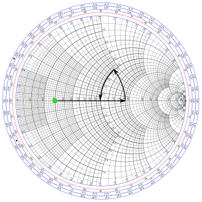
The gamma match by comparison is much more flexible, having three things to adjust. Well maybe 2½, because changing the diameter of the tubing is a bit tricky, though not as tricky as changing the length of the element.

On the Smith chart, the gamma match looks like this:

enter image description here

The Gamma match isn't super effective as a balun: it only increases the common-mode impedance by the factor of the impedance step-up it provides, which is probably in the neighborhood of 4 to 10. To avoid turning the Yagi into a vertical, some additional choking is probably a good idea.

$\endgroup$
1
  • $\begingroup$ Great answer!. I think I'll experiment with gamma matching then! $\endgroup$
    – hjf
    Commented Apr 14, 2020 at 20:05
1
$\begingroup$

Providing a single, simple answer to your question requires the design to be more completely specified. Designers who are unhappy with their antenna's performance may have unrealistic expectations. For a given feed strategy, coupling between parasitic elements can dramatically affect the match bandwidth, as well as gain, directivity and feedpoint impedance. Conversely, adding a secondary "sleeve" to the driven element (a la WA3FET's "Optimized Wideband Antenna" concept) can substantially restore match bandwidth.

In addition to the options you identified, the T-match is a balanced version of the Gamma match, for use with solid elements. If you plan to feed the antenna with coax, it's important to add a balun at the feedpoint to balance the currents.

$\endgroup$

You must log in to answer this question.

Not the answer you're looking for? Browse other questions tagged .