1
$\begingroup$

This is the insides of a common dual band antenna 2m/70cm, made by diamond or nagoya. its generally labelled as: 1/2 wave radialless (144MHz), 2 x 5/8 wave radialless (430MHz) Its meant to be ground independant.

Im trying to find the design name for the tuning/matching circuit at the bottom and how it works.

  • For example what stops the signal going down to ground at L1 rater than going up the elements ?
  • Does the coil below the C1 tap point provide the counterpoise/ground for the antenna, and the part of coil above act as matching/loading coil for lower element ?
  • calculators/plans around for this type or antenna ?
  • generally how does it work, im also trying to model it such as in 4nec2
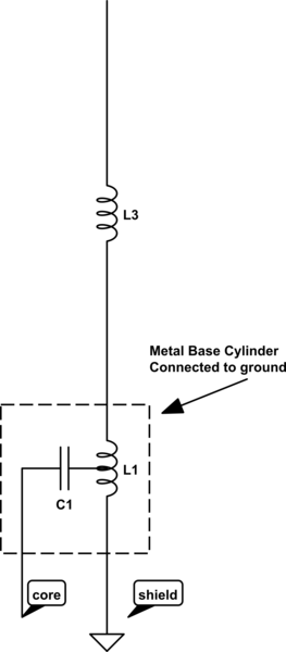
schematic

simulate this circuit – Schematic created using CircuitLab

$\endgroup$
5
  • $\begingroup$ Inductors will need to be modelled as parallel LC circuits, they will be designed to self-resonate somewhere near the bands of interest. $\endgroup$
    – tomnexus
    Commented Feb 3, 2021 at 7:27
  • $\begingroup$ Where is the feedpoint? Diagram says the "metal base cylinder" is connected to ground, but doesn't show the connection; are you sure they are shorted together? $\endgroup$
    – Brian K1LI
    Commented Feb 3, 2021 at 8:36
  • 2
    $\begingroup$ Also keep in mind that DC connectivity to ground does not mean RF connectivity to ground. Consider a simple loop antenna: at DC the entire thing is a short circuit, and yet if the loop is made one wavelength in circumference it can be a very effective antenna. $\endgroup$ Commented Feb 3, 2021 at 14:38
  • $\begingroup$ @BrianK1LI yes, the base that screws on to pl259 is a metal tube connected to gnd/shield, inside tube is the coil and cap. the antenna elements are then connected to the top of the tube which is plastic capped and has active come out of centre. $\endgroup$ Commented Feb 4, 2021 at 22:30
  • 2
    $\begingroup$ Background: The radiation resistance of such spiral-wound antennas (alone) is related to its physical length (end-end), which for a Nagoya NA771 is ~15-1/4" -- about 0.39 lambda at 146 MHz Coil L3 shown on your drawing is an attempt to zero out the reactance of that end-fed radiator, but does little to increase its radiation resistance. The network at the base of the radiator provides an ~tolerable match of the input Z of the antenna system to what the transmitter expects to see as a load: probably 50 ohms. $\endgroup$ Commented Feb 8, 2021 at 7:49

2 Answers 2

3
$\begingroup$

This arrangement:

schematic

simulate this circuit – Schematic created using CircuitLab

is called an L-match.

Adding a tap to the inductor creates an autotransformer which allows an additional degree of freedom in the tuning network. It's useful here because the impedance of the half-wave element is much too high; the autotransformer steps it down to something closer to 50 ohms, reducing the mismatch that must be corrected by the L-match.

This is very similar to an equivalent circuit for a gamma match, the only difference being the autotransformer is flipped around.

$\endgroup$
6
  • $\begingroup$ The L match calcs and circuit examples i find online have the cap tied to ground, not with the source in series. $\endgroup$ Commented Feb 15, 2021 at 1:57
  • 2
    $\begingroup$ @HaydenThring It's named an L-match because the two components make an L-shape. It's still an L-match with whatever components you put in there, and you can flip them around depending on if you want to step or down, or if you want a high- or low-pass characteristic. $\endgroup$ Commented Feb 16, 2021 at 21:46
  • $\begingroup$ Ok, thanks for your help. With how my diagram has the capacitor connecting part way along the inductor (as a tap?) would i model that by adding another inductor in series after the l match to account for the part of the inductor above the tap point ?? $\endgroup$ Commented Feb 16, 2021 at 22:16
  • 2
    $\begingroup$ @HaydenThring The tapped inductor is an autotransformer. You can't model it as a separate series inductor since that wouldn't model the shared magnetic flux. How you model it depends on what kind of model you are making. $\endgroup$ Commented Feb 18, 2021 at 15:32
  • 2
    $\begingroup$ @HaydenThring I don't know anything about 4nec2, maybe try asking a new question along the lines of "how to model an autotransformer in 4nec2". I'm sure other people here know. $\endgroup$ Commented Feb 18, 2021 at 23:11
1
$\begingroup$

The matching circuit looks similar to the type of N:1 balun/unun used to feed an end-fed half-wave without too great an impedance mismatch. Except in this case L3 shortens the dipole at its center, and the portion below half of L3 is the counter-pose to the quarter wave section above half of L3.

$\endgroup$
1
  • $\begingroup$ Oh, so i was maybe thinking about it wrong, so do the 2x 5/8 'halves' act as a 70cm dipole, not 2 individual stacked elements (collinear?) but can you have a dipole fed from the end ? is it then just a end fed and not a dipole... Id also assumed which i think is still correct that both elements act as one to form a 1/2 for 2m. $\endgroup$ Commented Feb 4, 2021 at 21:48

You must log in to answer this question.

Not the answer you're looking for? Browse other questions tagged .