11
$\begingroup$

How (and why) does a Gamma match work, when used on the driven element of a Yagi antenna? As shown here:

enter image description here

(source: http://www.iw5edi.com/ham-radio/?2-element-yagi-for-10-meters-band,49)

The article describes a 10 meter Yagi where the driven element is one continuous conductor and not the classic dipole-halves driven by 50 ohm coax. I have seen other designs where Gamma matches were used on split folded dipole elements joined on the far end. Clearly capacitance is the key, but I don't understand how it can work efficiently.

$\endgroup$
2
  • $\begingroup$ I make legal limit power mag-loops with a gamma match and no capacitor. It is my impression that the cap makes the match more frequency dependent and limits the ability to use the antenna on more than one band. The cap does make fine tuning easier. I have also used the gamma match to match vertical poles up to 125 ft with good effect even when the pole was a height adverse to the usual vertical antenna. These impressions are based on having matched dozens of antennas of various types. $\endgroup$ Commented May 17, 2020 at 4:34
  • $\begingroup$ Hi Wayne, and welcome to ham.stackexchange.com! BTW your post, although relevant and interesting, doesn't answer the question. The site is all about questions and answers, unlike forum-style sites. Anyway, we're glad you're here! $\endgroup$
    – rclocher3
    Commented May 18, 2020 at 13:56

6 Answers 6

15
$\begingroup$

A gamma-match serves a triple purpose:

  1. As a small diameter wire parallel and in close vicinity with the main radiating element, it will carry only a fraction of the main element current while being exposed to the same electrical field strength. This turns it in an effective up-transformer of the antenna input impedance.
  2. It also forms together with the main radiating element a closed wire stub, adding inductance to the antenna input impedance. If this is not required for matching, the additional inductance can be cancelled out with a lumped capacitor in series.
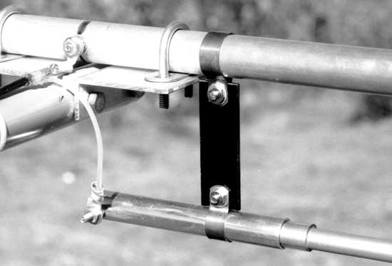
  3. Not shown on your figure but on the picture below: The sheath of the coaxial feed-line is connected to the center of the main radiating element. When properly connected, a gamma-match also serves as a balanced to unbalanced converter or balun.

All these functions are highly desirable for matching the unbalanced characteristic impedance of the coaxial feed-line to the much lower balanced impedance of a Yagi-antenna.

gamma-match detail

$\endgroup$
1
  • $\begingroup$ It's reasonably easy to entice common mode current down the feedline in contrast to point #3's suggestion. $\endgroup$
    – JSH
    Commented Oct 6, 2021 at 19:59
19
$\begingroup$

Clearly capacitance is the key

Capacitance is just one part of it. The gamma match in your question is three things:

  1. A sort of folded dipole, performing an impedance step-up
  2. A parallel shorted transmission line stub, adding shunt inductance
  3. A series capacitance

An equivalent circuit is:
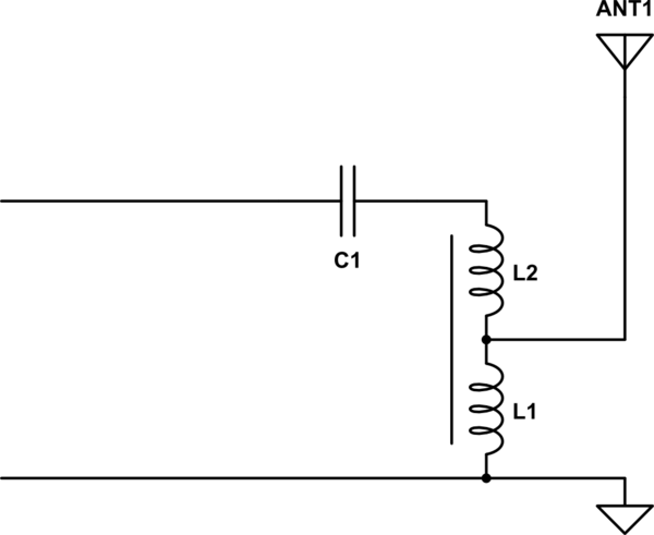
schematic

simulate this circuit – Schematic created using CircuitLab

So let's say we have some antenna with a feedpoint impedance of $(15+j0)\Omega$. On a Smith chart, we have this:
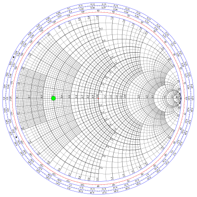
enter image description here

Our goal is to move that dot to the middle of the circle. How does a gamma match accomplish that?

sort of a folded dipole

The first point is probably the hardest to understand. Consider that in a folded dipole, the impedance is four times that of an ordinary dipole because the antenna current flows in both legs of the dipole, but only half of it in the leg where the feedpoint is. Since current is halved while radiation resistance remains essentially unchanged, impedance is quadrupled.

Now consider the gamma match: the same condition exists. Some of the current flows through the main antenna element, and some of it through the gamma bar, and this provides the same sort of impedance step-up. In fact, if you move the shorting strap all the way to the end of the antenna, it's exactly a folded dipole.

Typically, the gamma match is constructed to give an even more than 4:1 impedance step-up. By making the gamma bar smaller than the main element, the gamma bar will take an even smaller share of the total current. Even less current means a higher impedance transformation.

In terms of the equivalent circuit, the size of the gamma bar influences where the autotransformer formed by L1 and L2 is tapped. Here's the effect on the Smith chart:
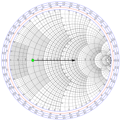
enter image description here

a parallel shorted transmission line

The gamma bar running parallel to the antenna element make a twin-lead transmission line. It's shorted stub, and less than $\lambda/4$ long, so it looks like an inductor. The position of the shorting bar determines the inductance, the value of L1+L2 in the equivalent circuit above.

If the shorting bar is moved all the way to the end of the antenna, then the susceptance is zero, and has no effect on the feedpoint impedance. As the shorting stub is moved closer to the feedpoint, it makes the susceptance larger, as if L1+L2 were becoming smaller inductors.

With parallel inductance added, our Smith chart looks like this:
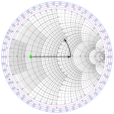
enter image description here

a series capacitance

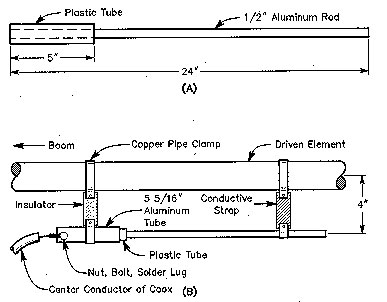
The capacitor is formed by the aluminium tube, with the gamma rod inside it, insulated by plastic. This is an optional feature of the gamma match, and it's not always present, or configured exactly this way. But with it, we can do this:
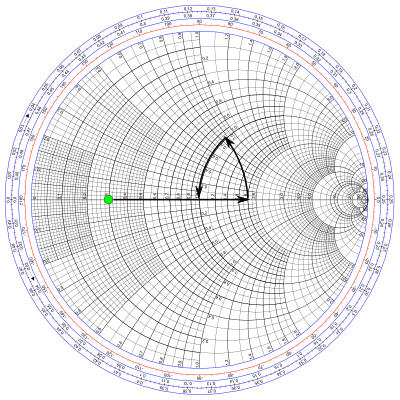
enter image description here

Mission accomplished.

As configured, C1 and L1+L2 form a step-down L network. It's also possible to trim the antenna to be a bit short, in which case it will provide some capacitance, but on the other side of the inductance. In this case, you get a step-up L network.

Since antenna can also be tuned to be exactly resonant (present a purely resistive feedpoint impedance), you don't technically need to add any inductance or capacitance: just the transformation from the first point is sufficient and you could have an ordinary a folded dipole. However this frequently isn't done in practice since adjustment of the impedance transformation requires changing the diameter of either the gamma bar or the antenna element, which is tricky.

It's also the case that the gamma match works somewhat as a balun. If it steps up the impedance seen looking in from the coax, by reciprocity it also steps down the impedance looking in the other direction back into the differential mode of the coax. The common-mode is left alone but is now a relatively higher impedance. So, it might be more desirable to step-up too much, then step-down with the L network. Even so, for an antenna with high directivity some additional common-mode suppression may be necessary: combined with the gamma match it may be even more effective. G8HQP provides a more complete explanation with all the math if you want more detail.
$\endgroup$
2
  • $\begingroup$ what a great explanation, oh look it's from my friend phil frost... what do you know :) $\endgroup$
    – pgibbons
    Commented Nov 8, 2020 at 3:37
  • $\begingroup$ Your answer is great. I've read that the center point of the driven element might not truly be a null caused by destructive interference. Does a choke on the outside of the coax help to support something close to a null at the center then ? $\endgroup$
    – wbg
    Commented Oct 15, 2021 at 23:34
2
$\begingroup$

The gamma match is problematic. It surely allows a perfect impedance match having two degrees of freedom, but the balun effect is questionable. The screen of the coax is connected to the center of a half wave element. That means that it is connected to two open-ended quarter-wave conductors. In free space they would have a very high impedance at the ends and consequently the impedance at the center would be very low. That means that the voltage on the coax screen would be very low so not much signal would be sent onto the screen of the coax (or not much qrm would be picked up if the coax has interference on its outside.)

A half wave dipole where two quarter wave rods are fed in anti-phase is a good radiator with Z=free space impedance (300 ohms) divided by about 6. But if one feeds them in phase, radiation from both sides will cancel and the impedance at the center goes towards zero while the impedance at the ends becomes very high. The midpoint becomes a good groundpoint.

In real life it is different. Practical experience: A friend of mine had an EME array with several long yagis on 144 MHz. They all had a gamma match which was isolated from the boom tube. There was however a performance problem. A simple test: Take one antenna, point it straight into the sky with the reflector well above ground. Put a field strength meter on the last director and look at the reading while moving the hand along the coax. Big variations were observed meaning that a substantial current is flowing on the coax screen. Add a sleeve balun. That makes the current on the screen negligible. That was long ago, but as I can recall performance was improved by more than 1 dB (That is a lot on EME) The explanation is that the physical midpoint is not the electrical midpoint. If you would make a dipole from two rods of different diameter and feed them in phase radiation would not cancel and consequently the impedance at the midpoint would not be very low. It would be necessary to make the thicker side shorter. The gamma match destroys the symmetry of the radiator so there is a substantial RF voltage at the center. This causes some loss of power and maybe more importantly pick up of conducted interference.

$\endgroup$
5
  • $\begingroup$ I don't follow your logic about attaching the screen to the center of a halfwave element. Why wouldn't you attach the screen to the center of the dipole? That point is ground, just like the screen. $\endgroup$ Commented May 2, 2018 at 18:26
  • $\begingroup$ Of course the screen has to be connected to the center of the (near) halfwave element that we feed with a gamma match. The problem is that the midpoint is not quite ground in a long yagi. That is an experimental fact and not a theoretical speculation. Presumably the reason is the assymetry of the structure. By placing a current choke (balun) on the cable one can prevent currents on the screen. (alternatively one could connect the screen to the zero-voltage point on the element which is a bit off-center. $\endgroup$
    – sm5bsz
    Commented May 3, 2018 at 21:10
  • $\begingroup$ I'm not saying a gamma match is alone a great balun -- at best, it only makes the common-mode impedance 10x or so what it would otherwise be. So I agree with your observation, but I'm pretty skeptical of your explanation. $\endgroup$ Commented May 4, 2018 at 0:35
  • 1
    $\begingroup$ You can easily simulate with NEC2. Design a typical 3 element yagi (to make the radiator impedance low as is normal in a yagi.) Then add the gamma match similar to the photo above. Close with a wire to the element midpoint and apply a current or voltage source there. Then add a quarterwave which is perpendicular to the dipole and to the axis of the yagi, Look at the current that the simulation will give on that quarter-wave wire. You can move the wire until you find the point where the current on the wire is zero. Alternatively, move the gamma match off center. $\endgroup$
    – sm5bsz
    Commented May 4, 2018 at 1:31
  • $\begingroup$ OK, I think I understand what you are getting at. I'd suggest making it more clear in the first paragraph that you are describing what should happen theoretically -- that threw me for a loop. $\endgroup$ Commented May 4, 2018 at 2:58
1
$\begingroup$

Consider, the impedance presented by any antenna element that's close to resonant varies along its' length from near zero at the boom to near infinity at the tip. Moving the tap allows you to select any impedance you desire.

The tap rod has inductance, and the series capacitor allows you to neutralize this inductance.

In short, a gamma match has two adjustments; the position of the tap on the driven element (which varies impedance), and the variable capacitor in series with the inductance of the tap (which tunes out reactance). With these two adjustments you can match any antenna that's anywhere close to resonant to any feedline impedance you want. That's why I LOVE gamma matches!

(I have seen only one antenna that had no capacitor, and it would only match at one frequency. The wrong frequency, as it turns out.)

$\endgroup$
7
  • $\begingroup$ But moving the shorting bar doesn't get you a transformer-like impedance transformation like moving the feedpoint of a series-fed dipole does. Rather, it changes the length of a shunt shorted stub, effectively an inductor. $\endgroup$ Commented Jun 28, 2014 at 14:12
  • $\begingroup$ Also, I think when you see antennas with capacitorless gamma matches, they are either not designed to be adjustable at all (instead, manufactured to pre-determined dimensions), or they provide a mechanism to adjust the element length, thereby changing the capacitance of the element itself (which will probably be a bit short to assure it is indeed capacitive) $\endgroup$ Commented Jun 28, 2014 at 14:15
  • $\begingroup$ What you call a "shorting bar" is a movable tap on the antenna element. Yes, it does have inductance, but that is incidental and an unwanted side effect. The series capacitance is used to neutralize this inductance (producing a series tuned LC circuit of zero reactance). $\endgroup$
    – HarveyB
    Commented Jul 7, 2014 at 3:18
  • $\begingroup$ Re: capacitorless gamma matches. That actually makes a twisted kind of sense, although as I said, I've only seen one and I'm pretty sure it was a mistake in construction. Have you any examples of commercial antennae without capacitors? $\endgroup$
    – HarveyB
    Commented Jul 7, 2014 at 3:30
  • $\begingroup$ If you do a Google image search for "yagi" you will see a few, although far more common is to use a folded dipole for the driven element, which is a balanced gamma match (T match) with the shorting bar / tap / whatever you want to call it adjusted for 0 inductance. If the stub is less than a quarter-wave long (as usual in a gamma match), then it does present an inductance, and you need a capacitance somewhere. It doesn't have to be a series capacitor though: it can also be a shortened antenna element. $\endgroup$ Commented Jul 7, 2014 at 12:36
1
$\begingroup$

A variation of the gamma match is a coupling loop antenna mutually coupling to the center of a dipole. A small single turn loop antenna is formed and as a very inductive loop, a series capacitor is inserted between the feedline and the inductor which will become resonant at a LOW impedance. (series resonant tank) When this is coupled to a solid dipole element, which also a low center impedance, a near 1:1 transformer ratio efficiently couples from the loop antenna into the dipole element. This loading raises the R value of the resonant loop to the feedline impedance. A gamma match has some quality of the series resonant tank circuit coupled to a driven element. In some designs, the match does not tap the element at a distance from the center, but instead is a loop that is only connected at the center point of the element. In this design, there is only mutual coupling as there is no direct electrical connection.

$\endgroup$
0
$\begingroup$

For a continuous conductor driven element, like the one in the article, the gamma match is basically a variable capacitor that is used to tune out any inductance from the (unbalanced) feeding of the antenna.

As the article states, the center of the driven element is a zero voltage point, so it's OK to ground the boom there and feed the braid side of the coax there (remember RF is AC, not DC). Attaching the other side of the coax further out on the element is going to create an impedance problem, of course, but that's what the match is for.

The major drawback of the gamma match is that it's there on the boom of the Yagi, in the air and therefore, inconvenient to adjust. You'll only want to use such a matching system where the SWR bandwidth of the resulting antenna is wide enough for your purposes. So you won't need to mess with it once the antenna is tuned initially.

You could replace the gamma match with a variable capacitor of the appropriate range. This is common in other types of antenna (e.g., loops) where the bandwidth is narrow and you need to tweak it up as you tune.

$\endgroup$
3
  • 1
    $\begingroup$ The gamma match is to match the feedline to the antenna. This is quite different from tuning the antenna to resonance, which is what the variable capacitor common in loop does. For example, see the image in How to make a loop antenna for HF?, which has a gamma match (on the feedline side) and a variable capacitor (opposite the feedline). $\endgroup$ Commented May 20, 2014 at 14:00
  • $\begingroup$ To be clear, certainly there are ways to do matching with a variable capacitor, but the most common use of a variable capacitor in a loop is probably not that, so I think the wording is ambiguous or misleading. $\endgroup$ Commented May 20, 2014 at 14:09
  • $\begingroup$ Reading this some months later, I have since come across some other people (like W8JI) which write about a "gamma match" as if it's just a series capacitor. The gamma match I know might have a series capacitor, but also always has a parallel shorted stub, and is also a special case of a folded dipole. It does a lot more than just a series capacitor. So I wonder, is there some other kind of "gamma match" that people talk about? $\endgroup$ Commented Jun 17, 2014 at 14:18

You must log in to answer this question.

Not the answer you're looking for? Browse other questions tagged .