1
$\begingroup$

It's simply a bromide amongst hams that you need to match the output impedance of a transmitter to the input impedance of an antenna, but I never thought through the implications of this until I came across this summary in a reputable textbook:

Of the power that is provided by the generator, half is dissipated as heat in the internal resistance (Rg) of the generator and the other half is delivered to the antenna. […] If the antenna is lossless (ecd = 1), then half of the total power supplied by the generator is radiated by the antenna during conjugate matching.

(Balanis, Antenna Theory, 1982 edition, p. 56)

Now in one sense of course this is true, because whenever we talk about "output impedance" we get this sort of picture (which I've cribbed from https://electronics.stackexchange.com/a/423884/9043):
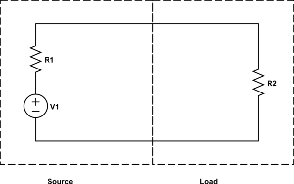
Schematic divided into two parts: a voltage "source" with its own resistor R1 versus a "load" with its own resistor R2

simulate this circuit – Schematic created using CircuitLab

And so when the "source" and "load" resistances are matched as we all know they "should be", it's inevitable that only half the power would make it to the load!

But this is also rather astounding! So basically the "ideal condition" (matched load to source) which we all know is required for "maximum power transfer" implies by its very definition a maximum efficiency no greater than 50% under any circumstance?!

I had noticed this relationship in practical transmitters I have, that they generally need more than double the DC input power than their maximum RF output power. But I assumed this was for a — completely different? or directly related? — reason: the efficiency of the amplifiers. Even from audio electronics I new that a Class A power amplifier was less than 50% efficient, and just figured maybe that was what radios tended to use, instead of the more efficient topologies, to maintain clean output signals.

Now when I learned about amplifier efficiencies in audio context (e.g. <50% for Class A, <78.5 for Class AB, ~80% for Class C, over 90% for Class D…) I assumed that was overall system efficiency. But with a amplifier "source" and matched speaker "load" wouldn't the same power transfer issue also come into play — that regardless of how "efficient" the amp is it always has to heat up at least as much as however much energy the load is radiating? So a Class D amp would really be 45% efficient within the overall system — i.e. 90% of the theoretical maximum of 50% efficiency?

Or are these two things actually somewhat related, the 50-50 power split between the transmitter and the antenna, really meaning the same thing as the 50% efficiency of a Class A amp? Because on the one hand, I can't see how we would say "a Class AB amplifier wastes only 21.5% as heat in transistor switching…" without also mentioning "…but then of course 50% of that is also wasted as heat in the amplifier's 'source impedance' anyway". But on the other, if we really can make amplifiers more efficient than 50% then how does that "match up" with what Balanis is saying?

$\endgroup$
2
  • 3
    $\begingroup$ Closely related (but not directly asking about "maximum efficiency"): How does the Maximum Power Transfer Theorem relate to RF power amplifiers? In brief: maximum power in the sense of the theorem is not maximum efficiency, nor is it necessary. $\endgroup$
    – Kevin Reid AG6YO
    Commented Nov 1, 2022 at 14:56
  • $\begingroup$ @KevinReidAG6YO Thanks, that's definitely relevant and (while I haven't yet gone looking for more confirmation/corroboration) it looks an answer to my question is mentioned as an aside in the answer there: that a real-world amplifier would likely be designed with a source impedance much less than 50 [or whatever target] ohms the load has, for pretty much the reasons that surprised me in the matched case (avoiding waste heat). $\endgroup$ Commented Nov 2, 2022 at 19:16

2 Answers 2

1
$\begingroup$

The maximum power transfer theorem (MPTT) assumes that the source impedance and voltage are fixed, and asks you what load impedance gets maximum power in the load, assuming that the source is an ideal (infinite power) source in series with a source impedance. As you note, this comes up with peak power transfer at 50% efficiency.

For the MPTT to apply, $V$ and $R_S$ are fixed. We can choose a value of $R_L$ to suit our setup; to make the equations nice to look at, we'll choose $R_L = nR_S$, and look at the effect of changing $n$; we know from this that $n > 0$ in the real world.

First, let's think about efficiency. Efficiency is power dissipated in the load divided by total power, but we want to get this in terms of $n$: $$ P_L = I^2 R_L = I^2nR_S $$$$ P_T = I^2 (R_S + R_L) = I^2(n+1)R_S $$$$ \frac{P_L}{P_T} = \frac{I^2nR_S}{I^2(n+1)R_S} = \frac{n}{n+1} $$ Nice and simple; as the load impedance gets larger relative to the source, efficiency improves, and more of our total output power is dissipated in the load.

But we also need to consider the actual power dissipated in the load. This means we need to determine the current in the circuit, and then we can use our equation for $P_L$ from earlier to get power: $$ I = \frac{V}{R_S + R_L} = \frac{V}{(n + 1)R_S} $$$$ I^2 = \frac{V^2}{(n^2 + 2n + 1)R_S^2} $$$$ P_L = \frac{V^2nR_S}{(n^2 + 2n + 1)R_S^2} = \frac{V^2n}{(n^2 + 2n + 1)R_S} = \frac{V^2}{R_S}\frac{n}{n^2 + 2n + 1} $$ Because $V^2/R_S$ is a constant, $P_L$'s behaviour can be described in three parts: when $0 < n < 1$, $P_L$ grows as $n$ grows. When $n = 1$, $P_L$ reaches a maximum. When $n > 1$, $P_L$ falls, and as $n \to \infty$, $P_L \to 0$.

We can also calculate $P_S$ (the power dissipated in the source) in terms of $n$: $$ P_S = I^2 R_S $$$$ P_S = \frac{V^2}{(n^2 + 2n + 1) R_S} $$

This just tells us what we expect from efficiency - as $n$ gets bigger, $P_S$ gets smaller.

In real radios, though, we don't bother with maximum power transfer; we aim for efficient power transfer. We have a fixed $R_L$, and a fixed $P_L$ (the radio's rated power), and we want to build a source to produce this efficiently. This means that the impedance of the radio is not matched to the output, and thus we get higher efficiency, but lower peak powers.

Looking at a random design I happen to have to hand, the output impedance is around 10 Ω, driving a 50 Ω nominal load. This gets us $n \approx 5$, and thus about 83% of power goes into the load by our previous maths. The power output into the load is about 2 W RMS, and the power dissipated in the source is about 0.4 W RMS. Total current draw is on the order of 200 mA RMS, and is quite manageable for the system to offer.

If we reduced the load impedance to 10 Ω, to get maximum power from the source, we'd be getting 14.4 W dissipated in the load instead of 2 W, and we'd have 14.4 W dissipated in the output amplifier instead of the current 0.4 W. We'd also be trying to provide 2.5 A RMS or so of current at the same supply voltage, which would hurt us, since the power supply is designed to give it 250 mA RMS.

Further, if we redesigned to have a 50 Ω output impedance, we'd still get 2 W out, but we'd now have 2 W of heat dissipated in the source, not 0.4 W, and we'd thus be using about 4 W input power, not 2.4 W.

With these two design points in mind, you can see why we'd design an output impedance of 10 Ω to feed a 50 Ω load - while (assuming components could tolerate the currents and voltages involved) we could have a 14.4 W output into a 10 Ω load, or we could design for 50% efficiency and a 50 Ω output impedance, we have no reason to do that - we are happy transferring 2 W efficiently using devices whose maximum theoretical power output (at the cost of efficiency, and assuming they could handle the currents or voltages needed) is 14.4 W.

After all that, why do we bother matching to a nominal impedance? Why don't we design our radios to tolerate a wide output impedance instead?

There's two separate answers:

  1. For receive, the radio is the load, and the antenna is the source - we want maximum power transfer from the antenna to the radio, so we design the receive stage to be 50 Ω impedance, and accept that 50% of the power that arrives is "lost" in the antenna (but as powers involved are tiny, this is fine, we just get a better SNR).
  2. For transmit, real devices can't tolerate infinitely high currents and voltages. If the antenna impedance is too low (which may still be higher than the peak power transfer point), the current becomes high, and devices fail (due to heating, if nothing else). If it's too high, the voltages become high for a given power level, and devices fail from overvoltage effects (insulation breakdown etc).

In theory, though, you could design your RF source to put out 100 kW safely into a 50 Ω impedance given a big enough mains power supply, but use the margins you've gained to let you output 1 kW safely into anything from 1 Ω to 5,000 Ω. We don't do this because the sorts of devices you'd need to do this are very expensive, compared to the easy option of designing to put out 1 kW into a 50 Ω impedance and using impedance transformation to match the antenna directly.

$\endgroup$
1
  • 1
    $\begingroup$ Wow, thank you! I'm really torn now because the currently accepted answer does answer the question in a good overview way with it's own nice asides. But this has a lot of really great supporting math re. the tradeoffs and also many extra details of its own :-) $\endgroup$ Commented May 3, 2023 at 23:17
4
$\begingroup$

A partial answer, more about matching than about transistor amplifiers:

you need to match the output impedance of a transmitter to the input impedance of an antenna

No this is the wrong way around. If you have control of R1, the source impedance, for maximum power transfer (and efficiency) you want it as low as possible. This is what you see in practice, with audio and RF amplifiers and also with Honda generators.

A true 50 ohm source impedance is only seen in lab equipment, where you need to be certain the forward power is the same into any load impedance, and this is usually done by having an attenuator right before the port.

Off the shelf transmitters will have an impedance specification, that they're designed and tested to work with. We chose or tune the antenna+transmission line to present 50 ohms to the transmitter because this is what the transmitter is designed for not for maximum power transfer.

In fact as its output impedance is probably quite low, a transistor amplifier would probably generate more power into a 10 ohm load than a 50 ohm load. This could overload or overheat the transistors, so most amplifiers have some sort of high-VSWR protection. (Though some just have high-current protection to protect against low impedance loads).

The discussion in Horowitz & Hill is correct for the circuit given, and it does describe what happens to very high and very low impedance antennas. But the theorem is for that simple circuit. You shouldn't assume that all transmitters labelled 50 ohms is made up of a low impedance voltage source and a resistor.

Two examples that might illustrate it further:

An electrical outlet, or a generator, might have a source impedance of well under 1 ohm. We don't try to match anything to it (though we can work out the maximum power, and we know that both an open circuit and a dead short don't absorb any power or get hot.

Secondly, I recently researched a class E amplifier (for a frequency modulated WSPR transmitter so it's just generating one RF tone). It has effectively a fairly high Q resonant output filter, which is periodically "rung" by a pulse of current from the active device. The transistor is turned hard on and off which makes its losses are quite small. Theoretical efficiency is very high and practical efficency of the whole system, DC to RF, is well over 80% (90% claimed to be measured in the article above).

$\endgroup$
1
  • $\begingroup$ Not maximum power transfer - maximum efficiency. Given a constant impedance for both source and load, power transfer is maximised from source to load when the two impedances are equal. However, efficiency at this point is 50%. Efficiency keeps going up as source impedance goes down, but power transfer also drops below the maximum possible. We don't actually care about maximum power transfer - we care about efficiency - so this is fine. $\endgroup$ Commented Apr 28, 2023 at 16:46

You must log in to answer this question.

Not the answer you're looking for? Browse other questions tagged .