12
$\begingroup$

In the audio realm, where cable lengths are insignificant compared to the signal wavelength, I would understand an impedance mismatch damaging an amplifier as follows:

Take an audio amplifier that can deliver 100 watts of power into an 8 ohm speaker driver. So under normal operating conditions, by P = R * I^2, there would be 3.5A of current flowing to deliver these 100W. If this amplifier were connected instead to 2 ohm speakers, it would need to pass 7A of current assuming it will still attempt to deliver this same 100W.

Viewed even more simply: a 2 ohm load tends to "short circuit" an amp designed for an 8 ohm load. Further to this logic, connecting the same amplifier to a 32 ohm load would not hurt it, as the resulting current would be smaller than expected.


With radio frequency, we don't really worry about the impedance being "too low" but rather "too mismatched" and we use SWR to represent this mismatch.

Why in RF is connecting a 500 ohm load i.e. 10:1 SWR, to my amplifier's 50 ohm output, considered equally bad as causing a 10:1 SWR by connecting a 5 ohm load instead?

Do the two 10:1 SWR cases cause amplifier failure for different reasons? I wonder if in the 5 ohm case it is just a simple "too much current" like in the audio case, but in the 500 ohm case the transmission line somehow ends up increasing the voltage beyond what the transistors can handle.

Does it make any difference if we eliminate the transmission line altogether, so that standing waves can't really develop? Would it be okay to connect a high-impedance antenna feedpoint directly to a transmitter without problems, whereas a low-impedance antenna might still cause an overcurrent condition?
$\endgroup$
3
  • 1
  • 1
    $\begingroup$ Not high SWR destroys radio, but very high voltage, or big temperature in PA stage. Both can be result of impedance mismatch / SWR. "High SWR damage" is only short expression $\endgroup$
    – Jacek Cz
    Commented May 7, 2016 at 6:24
  • $\begingroup$ Acoustic speaker impedance (almost resistance BTW) has character "minimal". In antenna has character "equal" (as posibble). For example acoustic amplifier cannot be damaged by open speaker cable. Deep differences $\endgroup$
    – Jacek Cz
    Commented May 7, 2016 at 6:28

3 Answers 3

9
$\begingroup$

The VSWR isn't the problem per se, it's just the impedance that appears at the transmitter's terminals. Take the load at the end of the transmission line, transform it according to the electrical length of the feedline, and put that equivalent impedance right at the transmitter's terminals and you will have the same damage.

A particular VSWR can result in a range of impedances. For example 5:1 on a 50 ohm line can mean 10 ohms, 250 ohms, and a range of complex impedances in between. Some of those impedances may damage the transmitter, others may not. But since the length of the feedline isn't known, it's safest to keep the VSWR low.

So why can a mismatched load cause damage? In summary, the transmitter's final stage is made of reactive components, that is components that store and release energy. These reactive components are selected to have the load absorb some of that stored energy. Without that load absorbing energy, the energy instead appears as a high voltage or high current to appear somewhere which may not be equipped to handle it.

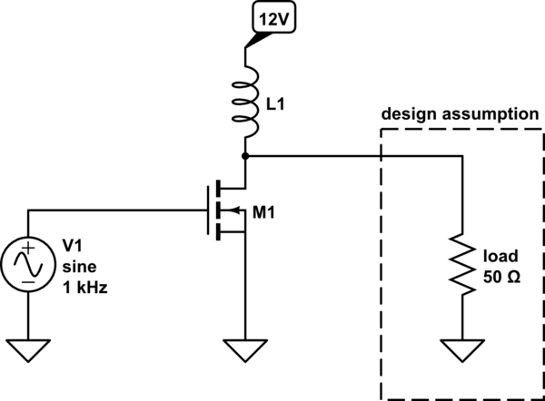
Let's give a very simple example to illustrate: a very simplified class-C common-source amplifier. You've probably seen such amplifiers with a resistor in place of L1, but for power amplifiers it's more common to use inductors to avoid the associated resistive losses.

schematic

simulate this circuit – Schematic created using CircuitLab

When the transistor is on, current through L1 increases and L1 stores energy. Let's say it's on long enough for current through L1 to rise to 1A. When the transistor is off, the voltage across the load will rise to 50V, because that's what it takes for 1A to pass through 50Ω. So we need M1 to have $V_\text{ds(max)} > 50\:\mathrm V$.

What happens if the load is open? Since no current can flow through the load, the voltage will rise even higher, whatever it takes to get 1A to continue flowing through L1. In this case it will be whatever voltage causes M1 to go into avalanche breakdown. RF power transistors aren't usually avalanche rated, so this means damage.

You can imagine other situations that lead to excessive drain current in M1 as well.

Of course, a real transmitter will be more complicated. It will probably have a low-pass filter on its output, multiple transistors with complex impedances at RF, and more reactive components within for impedance matching and filtering. All these values are selected with the assumption of a 50 ohm resistive load. Which load impedances will cause failure depend on the particular topology of the amplifier.

$\endgroup$
4
$\begingroup$

Since writing this answer, I've learned this explanation isn't entirely accurate. I'm leaving it because it's not entirely wrong, either.

Ultimately, it is impedance mismatch (really, too low an impedance) that damages transmitters. The thing to realize is the impedance seen by the final power transistors in the amplifier (the part that usually breaks) isn't the same impedance at the amplifier's terminals.

The reason is that amplifiers contain filters on their output to filter harmonic suppression, among other things. These filters are designed with the assumption of a 50Ω resistive load. When that assumption holds, the filter presents the design impedance to the finals, which the designer has determined will not smoke the transistors.

When the load is not 50Ω, the design conditions are violated and the impedance presented to the finals could be anything. If you get lucky, it will be a high impedance which just means the amplifier can't deliver its full rated power. If you get unlucky, it's a low impedance which draws too much current and overheats the transistors. It's hard to predict where you will get lucky, and where you will get unlucky without knowing the details of the transmitter's filters. Here's an example from Is there an optimum transmission line length for maximum power transfer?

enter image description here

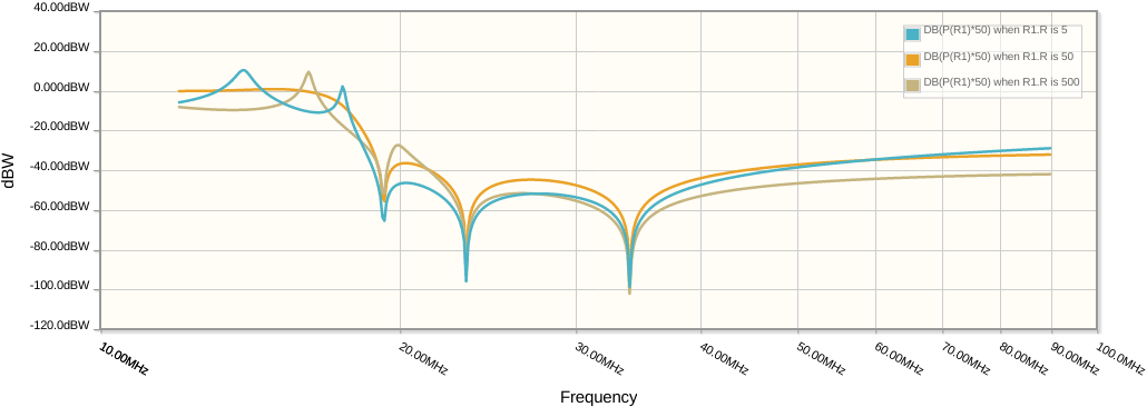
This is a 30/20m filter, so it is intended to pass up to about 14.4 MHz and attenuate all the higher harmonics of that. The orange line shows the case where there's a matched 50Ω load, while the blue and tan lines show 500Ω and 5Ω loads which are two cases of a 10:1 SWR.

Notice how the mismatch introduces peaks in the frequency response. Where these peaks are above the orange line, the amplifier is seeing a lower impedance, thus a higher current and more power. Here's the potential for damage. One of those blue peaks is right at 14 MHz and is about 10dB above the orange line. So on 20 meters, a 100W amplifier is suddenly trying to produce 1000W into a low impedance, which will quickly damage it.

There are any number of impedances which will result in a 10:1 SWR, and depending on the transmission line you might get any of them. I suggest checking out a Smith chart tutorial to get familiar with how this works.

This is why SWR is used to quantify the quality of the match: it is independent of transmission line length. For any given SWR, the height of those peaks in the graph above are about the same, and moving around different impedances with the same SWR just changes where they lie. Since you really don't know where they lie in practice, it's just best to avoid high SWR generally.

$\endgroup$
1
  • $\begingroup$ @Noji Why does it have to be one or the other? There are many amplifier topologies, and there's more to impedance than "high" and "low", and transistors have a whole table of maximum operating parameters which include current, voltage, and temperature. Given all these variables I'd expect there's more than one way to damage a transmitter. $\endgroup$ Commented Jan 28, 2021 at 15:09
1
$\begingroup$

Transmitters provide different levels of power, efficiency and distortion as the load changes. This is studied using a technique called "load pull" by applying different loads to the transmitter and noting the effect on the three things mentioned above. Then output networks are designed to provide the most optimum trade off between these three things. For a transmitter which operates over a wide frequency range such as 1.8 to 30 MHz, this optimum load will vary somewhat with frequency. Therefore circuitry is made as broadband as possible to optimize the load over this range. At a given frequency and power level, changing the load seen by the transmitter by using an antenna tuner, for example, could further optimize this three way tradeoff, but the operator would have to monitor power output(easy to do) efficiency (somewhat harder to do) and distortion (quite hard to do). Therefore it is best to assume that 50 ohms resistive load is the best to use at all frequencies and power levels. Transmitters sort of force you to do this by backing off the power when the SWR is high, meaning the load is not 50 ohms. Bypassing the "SWR foldback" and tuning for maximum output power is likely to cause efficiency and distortion to suffer more often than not. In a similar manner, tuning for best efficiency or distortion would probably reduce the power more often than not.

Getting back to the original question, IF one could monitor efficiency, power and distortion, one could tune at a given frequency and power level to make the transmitter run cooler with acceptable power and distortion. This would represent the case where the load resistance AT THE OUTPUT DEVICES was somewhat higher than normal, just like the case of the audio amplifier. In practice this is quite impossible for normal wide band transceivers, which are always operating in somewhat of a compromised condition.

$\endgroup$

You must log in to answer this question.

Not the answer you're looking for? Browse other questions tagged .