4
$\begingroup$

How much do transceivers drop their output power, when the SWR is high?

Most amateur solid state amplifiers or transceivers are (fully?) protected against high SWR, by a circuit which reduces the power and protects the final transistors.

In a $50\Omega$ system an infinite SWR implies a voltage of about double the Voltage (at 1:1 SWR), or a current of about double, depending on the phase. An SWR of 1.5:1 is only 1.2 x peak voltage or current. As you don't know the phase of the load, or how far it is down the line, the amplifier could see any of these numbers, with the extremes being more likely.
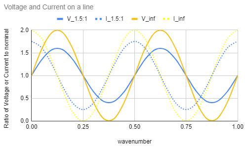
line voltage
So to prevent the final transistors seeing an unreasonable voltage or current from an open or short circuit, the power needs to be reduced only to half. This graph shows the voltage ratio and the "safe power" assuming there is no other safety margin in the transistors:
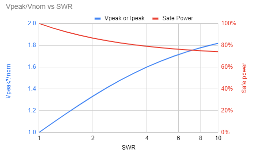
safe power

Laboratory amplifiers produce full power into any load, but these are about 100 x more expensive than amateur amplifiers.
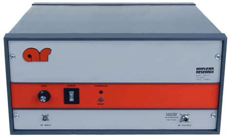
AR amplifier
It's obviously desirable to have as much power as possible, even when operating into a mismatched load, to keep the system as flexible as possible.

Has anyone measured how much the power drops on a transceiver with higher SWR? Ideally for different phases of high SWR, not just one.
$\endgroup$
2
  • $\begingroup$ Class A Amps must dissipate max power with no load, so they added bulk heatsinks and tranny heat sharing can withstand any mismatching from 0 to 10% efficiency from worst to best case matching. while Class AB can be 0 to 50% efficient while worst case can be 5x no load power loss thus foldback power limiting reduces operating power with mismatch because the Class AB are designed for lower power heat handling. $\endgroup$ Sep 19, 2020 at 16:05
  • $\begingroup$ Class A drivers thus reduce loss from 100% to 90% for 10% Pout with high linearity while Class AB is very load sensitive with up to 5x Pout with 50 Ohm load for up to 50% efficiency that reduces with reactive loads and thermally folded back to cut max internal dissipation and also Pout. $\endgroup$ Sep 19, 2020 at 20:28

2 Answers 2

4
$\begingroup$

Radio amateur transceivers differ a lot, their finals differ a lot, too. But their SWR protection mostly start somewhere between 2:1 and 3:1, some of them are even more touchy, and they mostly have quiet steep foldback characteristics - for a reason described later. Also, there can be differencies when the internal tuner, if exists, is turned on or off.

Some of them measure only the reflected energy, not the ratio, some of them have only a comparator and shuts down the P.A. entirely for a while or until a reset button is pressed - homebrew units tend to use these latter solutions.

So, why limiting the current the final stage may draw is not enough? Because this statement is not true: "So to prevent the final transistors seeing an unreasonable voltage or current from an open or short circuit, the power needs to be reduced only to half."

Analyzing the whole situation would take a lot of times and you can find great descriptions on the web, also, I'm not the best person for it, but usually there is not only one reflection in a real system, nor only resistive load(s) are there, which is an even worse phenomenon than the first one.

When a radio wave reflected by the antenna is travelling back on the transmission line, it will probably be reflected again when it reaches the power amplifier (unless they match prefectly) and starts going toward the antenna again through the transmission line, and despite of its reduced energy caused by this subsequent reflection, it also has voltage maximums and minimums, and so on.

Also, if a load is reactive, there will be capacitive and inductive maximums as well along the feedline, and it de-tunes the generator. A peak current at it can be handled fairly easy, but this is not true for the superimposed voltage peaks, which for example try to drive more current if a final stage transistor is open at that moment, and so. We are not speaking of just 20-30 percent overvoltages, things may go out of control easy, otherwise I haven't had to see a couple of arching capacitors and RF connectors in my life. :-)

$\endgroup$
2
$\begingroup$

My Icom T81 handheld has a detailed circuit diagram and description in the service manual which can be found online (well done Icom!).
It shows how the handheld will fold back power when the SWR is high:

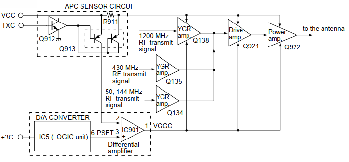
The APC circuit protects the power amplifier from a mismatched output load and stabilizes the output power. The APC circuit is designed to use VHF, UHF and SHF bands commonly. Icom Manual diagram The APC sensor (R911) detects driving current from the drive voltage at the YGR, drive and power amplifiers. The detected current is converted into a DC voltage at Q913, then applied to the APC control circuit (IC901, pin 2). The applied voltage is compared with a "PSET" voltage from the CPU via the D/A Converter (LOGIC unit; IC5) and the APC control circuit outputs "VGGC" voltage from pin 1 to control the YGR, drive and power amplifiers.
When the driving current is increased, input voltage of the differential amplifier (IC901 pin 2) will be increased. In such cases, the differential amplifier output voltage (IC901 pin 1) is decreased to reduce the driving current.

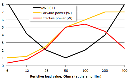
This circuit measures only the supply current to the amplifiers (dominated I suppose by the power amplifier), and by comparing it to a pre-set voltage (which you would program into the radio to yield 5 W). It will reduce the output power immediately if the PA current increases (even slightly), to protect the transistor. It will not reduce power if the current decreases, in fact it might increase it slighty. In a handheld radio, I assume the final transistor will have plenty of margin against high voltages, it's high current that could be a problem.

Thus I would expect the radio to have a output power graph something like this (based on a 5 watt nominal power rating and guessing a bit):
enter image description here

This means for a mismatched antenna, at a particular frequency, there is a cable length that will optimise the transmitted power by presenting a high impedance to the transmitter! And it can be found by searching for the cable length that causes maximum DC supply current to the radio.

Other references or hard data is/are welcome of course!

$\endgroup$
1
  • $\begingroup$ I'm glad that you tracked this information down! Having an inexpensive circuit to protect against high current, but not high voltage, makes sense. Now I know. $\endgroup$
    – rclocher3
    Jan 4, 2022 at 23:00

You must log in to answer this question.

Not the answer you're looking for? Browse other questions tagged .