1
$\begingroup$

I'm working on an old school VFO for the 15 meter band based on a JFET Hartley oscillator. The plan is to follow the oscillator section with a JFET buffer, then a CB amplifier (for increased reverse isolation) and finally, a feedback amplifier for gain.

The oscillator and buffer stage are complete and working well. But, I'm having some issues with the CB amplifier.

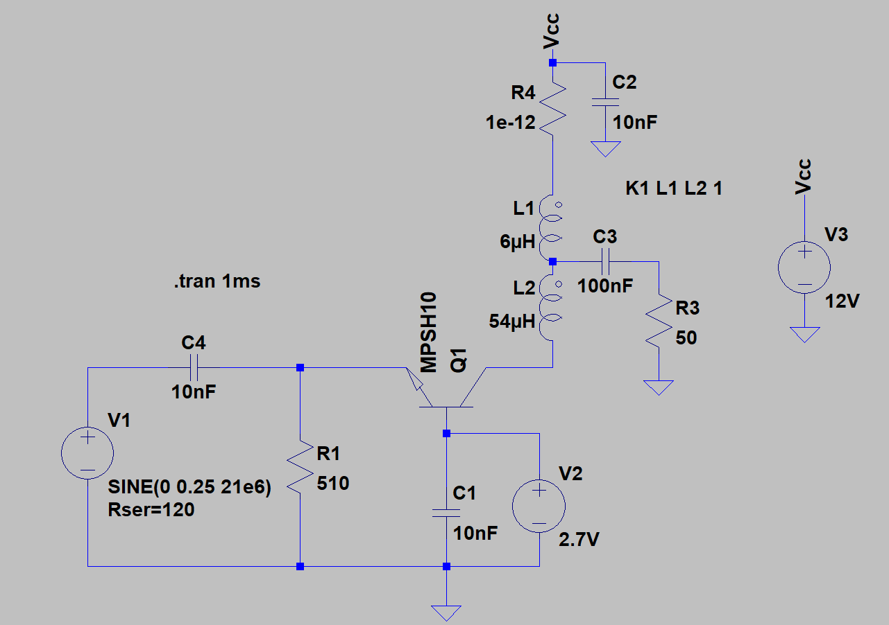
schematic

simulate this circuit – Schematic created using CircuitLab

In the schematic above, the buffer output is represented by V1. I measured it's output impedance to be ~80 ohms (it has quite a high trans-conductance). The impedance seen at the CB emitter should be about 26mV/4mA||510 or ~ 6.7 ohms.

The (theoretical) gain of this amplifier should be (50 ohms x (n^2))/6.6 = 68 approximately. So, you would expect to see 20mV p-p x (68/3) across the 50 ohm load or something just shy of 0.5 of a volt.

Instead, having built the circuit and after taking some measurements, I get about 240mV or half the gain. What seems to be happening is that the transformer is not "transforming" like it should. If I test the transformer using a signal generator, I get a transform ratio of 3:1, as expected. However, in-circuit it's more like 1.66.

Interestingly, the BJT is fulfilling its duty nicely: if you consider that a turns ratio of 1.66 makes 50 ohm look like 138 ohm at the collector. Then 138 / 6.6 = 21 approx. Then (20mV x 21) / 1.66 = 250mV which is very close to what I see across the load.

I'm just a bit stumped as to why the transformer is not behaving itself. I've used these type 43 cores before without issues and I even tried a bigger core size (same material) and I experimented with bigger values of C2. No change.

Also, the transistor is not a BC546 but rather a high frequency transistor pulled from a radio front-end. I've tried various HF transistors in its place with the same result.

Is there something about the CB amplifier that I'm overlooking?
$\endgroup$

2 Answers 2

6
$\begingroup$

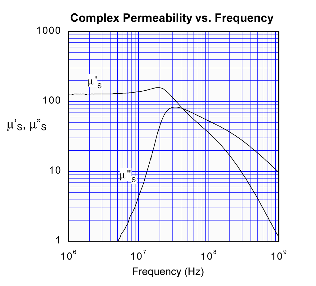
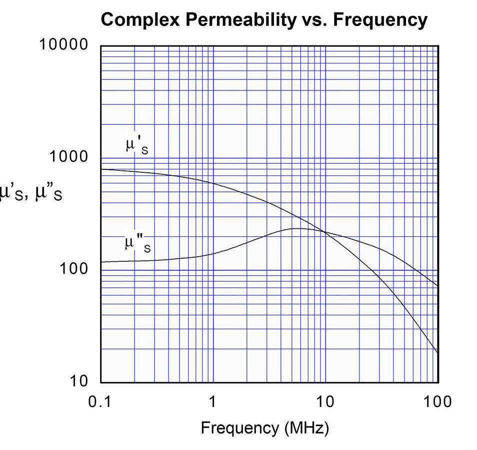
The problem is most likely the type 43 core material. It is quite lossy at 21 MHz and is a poor choice for the auto-transformer. Unlike a transmission line transformer, the auto-transformer relies on the coupling of the two coils to partially occur by passing flux through the core. The complex permeability of type 43 material indicates high losses for this flux at 21 MHz.

The effect of this core loss can be modeled as a loss resistance in series with each winding of the transformer. This would account for the apparent poor transformation ratio you are observing.

Type 43 Material

A much better core material selection would be type 61 which is suitable up to ~25 MHz. This material has a lower initial permeability (125 vs 850 for type 43) so you may wish to increase the number of turns in the correct proportions in order to ensure sufficient inductive reactance in the windings. Due to the low power involved, a large core geometry is not warranted.

Type 61 Material

$\endgroup$
2
  • $\begingroup$ Good info Glenn, I don't think I have any type 61 cores so I'll need to put in an order. Where did you get the graphs? $\endgroup$
    – Buck8pe
    Commented Feb 25, 2019 at 19:30
  • 1
    $\begingroup$ @buck8pe I clipped those from data sheets from Fair-Rite. $\endgroup$
    – Glenn W9IQ
    Commented Feb 25, 2019 at 19:32
1
$\begingroup$

I thought I'd come back to this having discovered the real reason why I wasn't developing the expected voltage across the 50 ohm load. Glenn's answer was good and is still very relevant, but I made a silly and simple mistake and I'd like to post it up as an answer in case someone else has the same issue.

Basically, I had reversed the windings on the toroid. This wasn't obvious on the schematic, but I had the major winding towards the power rail and the minor winding towards the collector. Since the power rail is AC grounded, this puts the major winding (8 turns in my case) in parallel with the load and gives an impedance transform of 2.25 or a collector impedance of roughly 112 ohms. This reduces the CB gain substantially.

This is how I should have wired it:

enter image description here

This is a real "trap for young players" since it seems quite intuitive to have the minor winding where I had it. I guess the golden rule is - always look for ground. Cheers!

$\endgroup$
1
  • $\begingroup$ Why not use a 9:1 Ruthroff transformer? A trifilar winding on your FT37-43 core would work perfectly... $\endgroup$ Commented Oct 11 at 22:10

You must log in to answer this question.

Not the answer you're looking for? Browse other questions tagged .