6
$\begingroup$

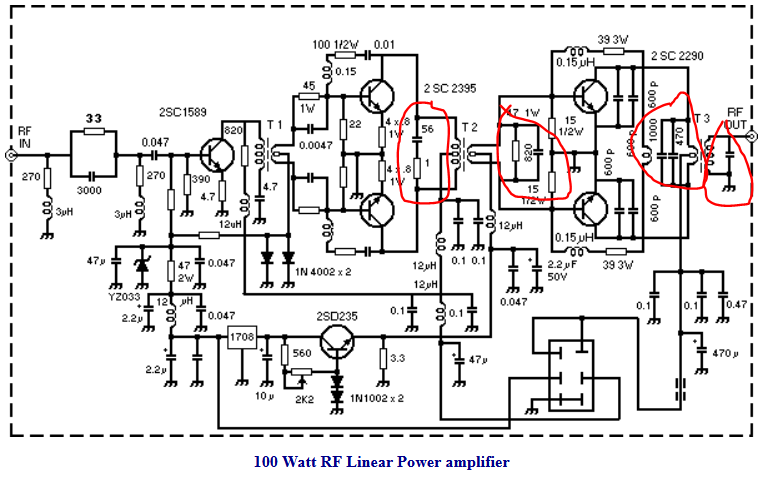
I keep finding RF push-pull power amplifier designs specified with a small(-ish) capacitor across the primary (or secondary) windings of the coupling transformers. Here's an example:

enter image description here

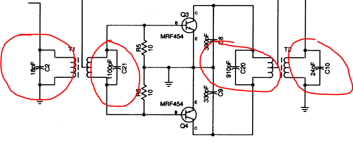
This is one example with capacitors across all windings, but I find them across the primary of the output transformer (the winding connected to the collector/drain of the transistors) most often.

Here's another example, this one with damping resistors either in series or parallel:

enter image description here

I'm assuming that this forms a resonant circuit of some kind and I'm assuming that they play a role in filtering harmonics, but I'm just not sure.

So, here are my questions:

  1. What is the benefit of having these capacitors (in the context of a PA)?
  2. Are they more effective in amplifiers cut for a particular band or are they also useful in broadband transceivers?
  3. How do you calculate what the value should be?

73
$\endgroup$
4
  • 1
    $\begingroup$ a guess: they are there to null out the inductance of the transformer windings? $\endgroup$ Commented Nov 27, 2021 at 8:16
  • 1
    $\begingroup$ @niels Nielsen Hmmm, not sure Neil's. My guess is that the capacitor resonates with the winding inductance to peak power transfer at the resonance frequency. It aught to reduce harmonics in the same way any tank circuit would (I'm guessing?) Thing is, they're often specified in broadband amps, which confuses me and it's not clear how the values are chosen? $\endgroup$
    – Buck8pe
    Commented Nov 27, 2021 at 16:16
  • $\begingroup$ Agree with both of you, they must be to compensate for / resonate with the magnetising inductance, which of course is frequency dependent. Resistors must be for something else. $\endgroup$
    – tomnexus
    Commented Nov 27, 2021 at 19:16
  • $\begingroup$ I thought the parallel cap is present to make sure the transformer transfers full current in phase with the amplifier. I suppose that is equivalent to making it resonant. When in school I partially built a Norcal40A according to the MIT Rutledge book and I tuned the output transformer to peak current. Antonio's answer about series caps also makes perfect sense. $\endgroup$
    – wbg
    Commented Jan 22, 2022 at 18:20

2 Answers 2

1
$\begingroup$

If these are broadband (toroidal, coupling ~ 1.0) transformers, then the capacitors in series with the resistor can be used to dampen the resonance that takes place at the edge of the band (higher frequency side).

One can see a peak in the transfer curve in the below picture.

So, the capacitor with the serial resistor (left 1 Ohm + 56 pF) can damp the peak at the highest frequency.

enter image description here

$\endgroup$
1
$\begingroup$

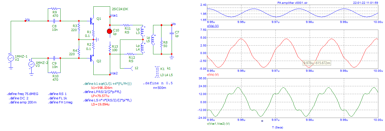
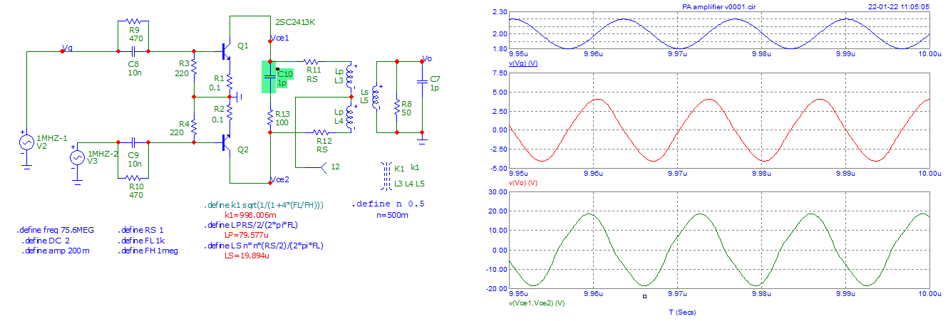
I have tried to simulate a part of this PA, where the serial capacitor with resistance is present (not the same value). I found also something interesting despite the difficulty of simulating ... (AC Analysis was weird).

Inserting this serial C+R makes the output (Vce1 to Vce2) "waveform" better. Perhaps also a "side" effect.

Here are the two pictures (Transient analysis). Frequency test 75 MHz with 2SC2413 transistors. (2SC2395 not in database).

enter image description here

enter image description here

$\endgroup$

You must log in to answer this question.

Not the answer you're looking for? Browse other questions tagged .