I'm working on a design for a home-brew 10 metre transmitter for CW. My oscillator is running cleanly, and I need to add a (small, probably 1/2 ~ 1 Watt) power stage to it, and I need to "modulate" the signal--i.e. turn the output on and off :) I want this to be simple, but I also want to avoid a bunch of splatter during keying. I'm sure this must have one or more very standard approaches by now, but I've not found much information on the topic. In particular, I want to find a reasonable compromise between simplicity and clean signal. I would therefore appreciate guidance.
My thoughts so far are:
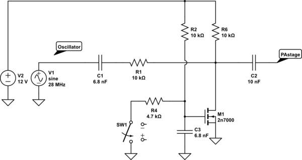
- (EDIT) I think my simplest "good" route might be to put what amounts to a variable voltage divider (using a FET) between the oscillator output and the PA input. I figure I might use the key into the FET's gate, with some capacitance to soften the transition from on to off. Something like the sketch below. I've given no thought yet to the time constants on the switching of the FET, but that part I know I can handle :) However, I'm not sure how well this might work. I think I need both decoupling capacitors in the feed path between the oscillator and the input to the PA stage, but I suspect I'll need to provide some bias for the part of the path where the FET sits, otherwise, after dragging the level down to ground, it'll have no reason to return to a level that's above the gate voltage, and ... well, I'm pretty weak with FETs, but I don't think that's good. There might well be other issues here--please speak up and feel free to ridicule this if you have comments!

simulate this circuit – Schematic created using CircuitLab
build a single-transistor amplifier stage, and simply use the key to connect the oscillator output to the amp input. My concerns here are: 1) that the switch on/off, if it happens in mid-cycle (which seems virtually guaranteed) will create a very sharp rise or fall, and that will create splatter. 2) If the input impedance isn't high enough, might I pull the oscillator off frequency? (It's crystal controlled, but still).
as above, but with an emitter follower buffering to keep any "pulling" to a minimum. This obviously doesn't address the mid-cycle switching, and indeed might make it worse.
make the amp a regular common emitter, but with a FET in the emitter line, acting as a switch to introduce the lower of two parallel resistors defining the gain. I think this way I can effectively turn the gain of the output stage down to "very low" (although not completely off). I think I could also introduce a time constant into the on/off switching of the gate to "damp" the transition between output and no-output.
use a dual gate FET type device. This seems to have two problems. 1) I've never used one before, so there's far more unknown quantity involved, and 2) The options for such devices I've managed to locate so far are both limited and all SMD (I'd rather use old-world through-hole if possible!)
What would you suggest? One of these options, or something else entirely?
Update January 2022.
I've been playing with a dual gate mosfet from AliExpress, specifically a 40673. It's clearly "venerable", and most places seem to think it's end of life, but I got ten for a little over $20, and it seems that if I put the RF into gate 1, and bias that to 0V (source level, in other words) and bias gate 2 to +4, with a 2k resistor in the drain line, it'll give some voltage gain (maybe x2, not much, but with a great input impedance, and low output impedance). But then, if I drag g2 to about -4V relative to the source, it shuts off the output entirely. A little RC timeconstant on that should do the trick to soften the envelope. I've not actually implemented this yet, but the breadboard tests are looking very promising. I imagine there are lower device-count ideas, and ideas using more "traditional" components, but as a learning exercise with a decent behavior, this is looking very promising.
