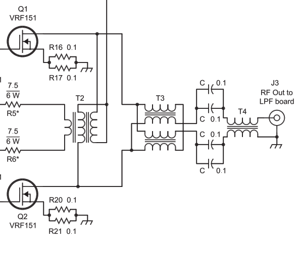
I want to base the output network for a 500W push-pull HF amplifier on "A 250W Broadband Linear Amplifier" described in Chapter 17 of the 2014 ARRL Handbook. I need advice on whether and/or how the 1:4 impedance step-up transmission line transformer should be modified to handle twice the originally intended power.
The long-form article included on the companion DVD shares the rationale for the transformer:
The advantage of the transmission line type of RF transformer is that it does not have the leakage reactance that plagues the tube-and-sleeve type of transformer used on many solid-state amplifiers.
Simulation documents the significance of this statement: even with compensation, the gain falls off with increasing frequency when the coupling factor of a conventional transformer is reduced from the ideal value of k=1.
T3, the output transformer for this 250W PA, comprises two (2) separate ferrite-loaded 25$\Omega$ transmission lines whose inputs are paralleled on the low-Z side and connected in series on the high-Z side:
The transformer calls for miniature coax such as p/n D260-4118-0000 wound on Fair-Rite 2861010002 binocular cores. How can I determine, a priori, whether this transformer can handle a 500W output level? If it can't handle 500W, how do I determine what changes I need to make to the coax and ferrite components?
Is calculating power dissipation as simple as noting the resistance component of the impedance from the data sheet and multiplying that by the square of the product of the current and the number of turns? How do I convert that into temperature rise for the core?
