4
$\begingroup$

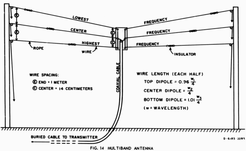
drawing of a fan dipole, taken from PDF file listed below

I built a fan dipole according to the basic instructions in the SRI publication describing the theory and basic design.

My questions is about next steps in tuning for the various bands. I am primarily interested in the phone / image range of the band as a General (KN4MIO).

Specific questions are bold below. I apologize for including multiple questions but I felt the topic of tuning and the context of the various bands were better presented in a single question.

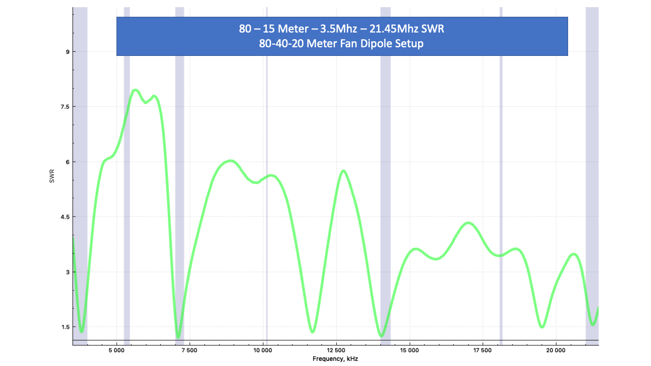
I did some basic tuning while on the ground and received some satisfactory results. I then positioned the antenna approximately 85' off the ground suspended between two trees and took some additional measurements. The SWR across the 80 - 15 meter range was tested and the results were good for a first pass. The shaded areas are the various bands. The second from the left is 60m can can be ignored.

Here is the SWR measured across the whole range from 80 - 15 meter enter image description here
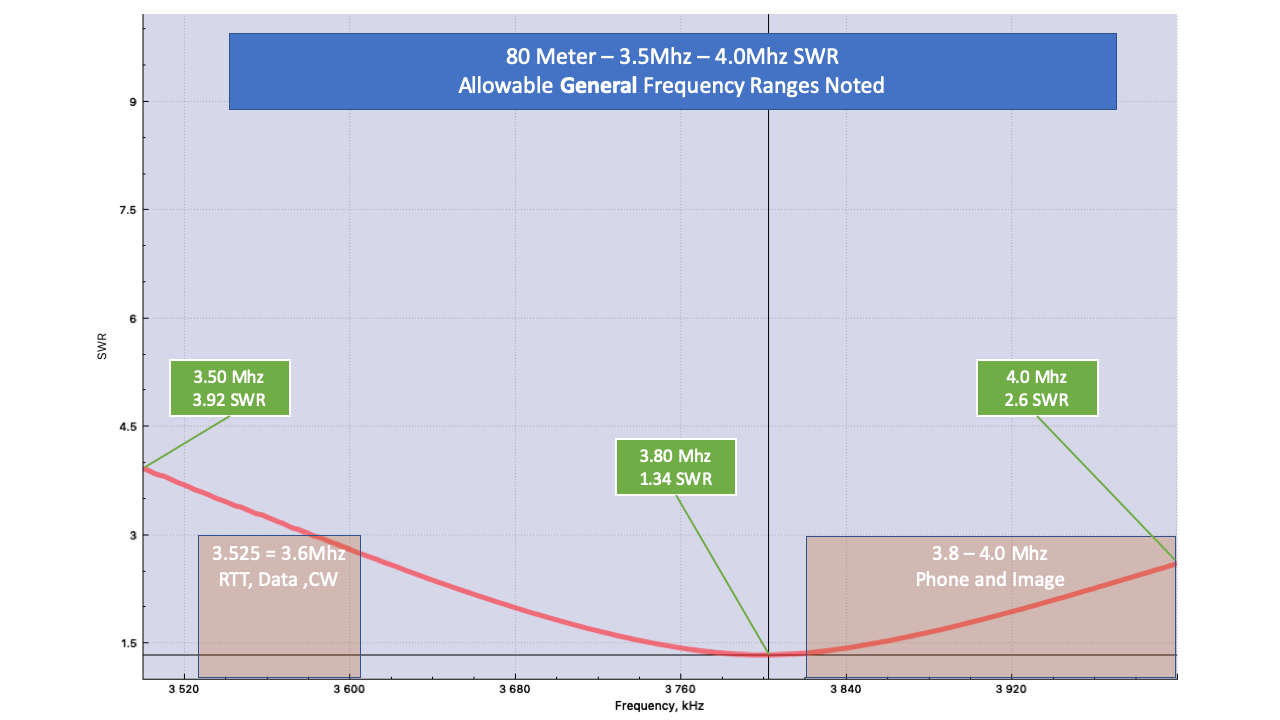
The 80 Meter band is shown below scanning from 3.5 - 4.0 Mhz.
enter image description here

The SWR for this band is tuned at the low end of the phone / image area at 3.8 Mhz. My understanding is that I can shorten the 80 meter antenna length to shift the SWR into the mid-range of the phone band.

Is there a way to flatten the SWR in this range or is this graph typical?
Is shortening the antenna the proper way to shift the SWR to the right?

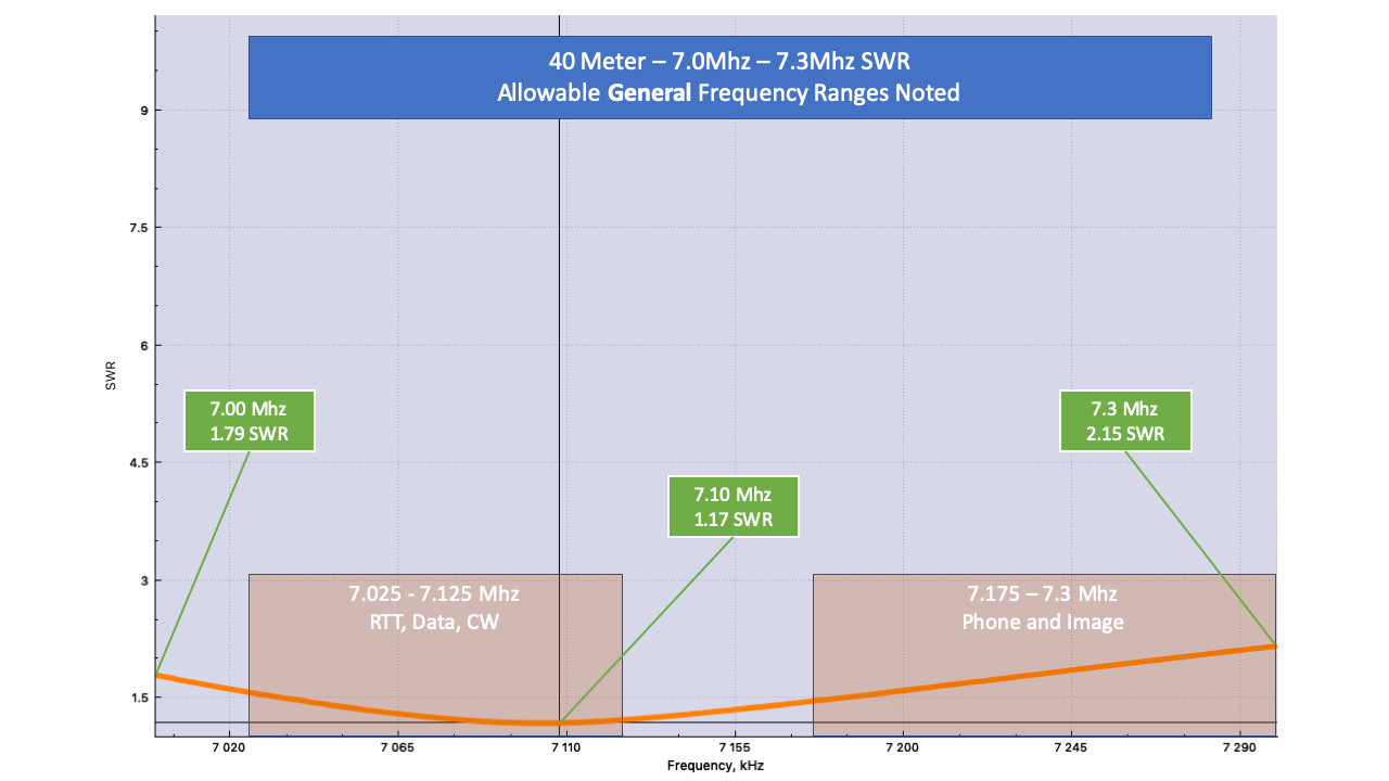
The 40 meter band is presented scanning from 7.0 Mhz - 7.3 Mhz. enter image description here Before adjusting the 40 meter I would complete the tuning of the 80 meter first. Given the lower SWR is to the left of my target shortening the antenna seems to be the means to shift the SWR to the right, correct?
Following are the 20 and 15 meter SWR scans. enter image description here .
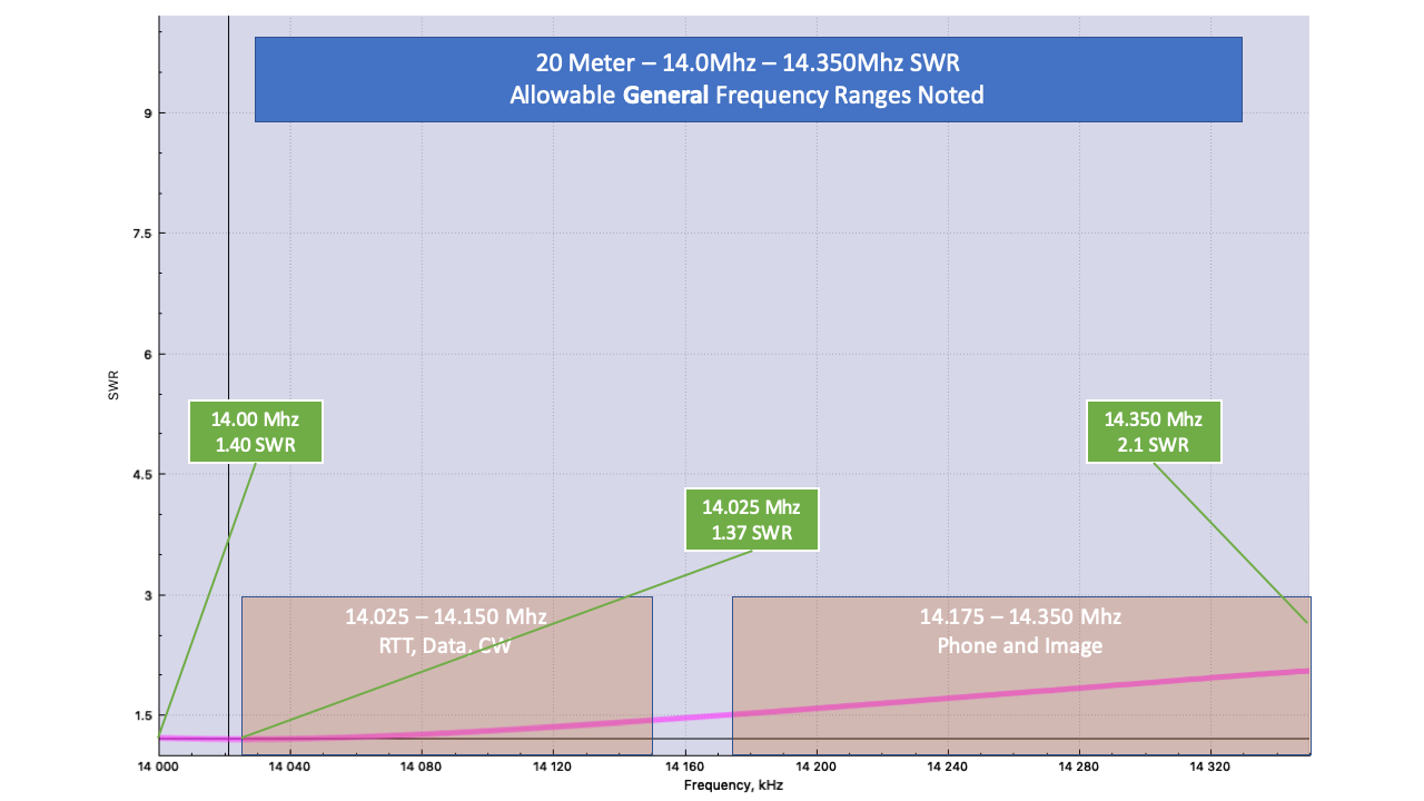
I was surprised that in the same way as the 40 meter being further to the left it seems like the 20 meter is following closely and shifting further to the left.
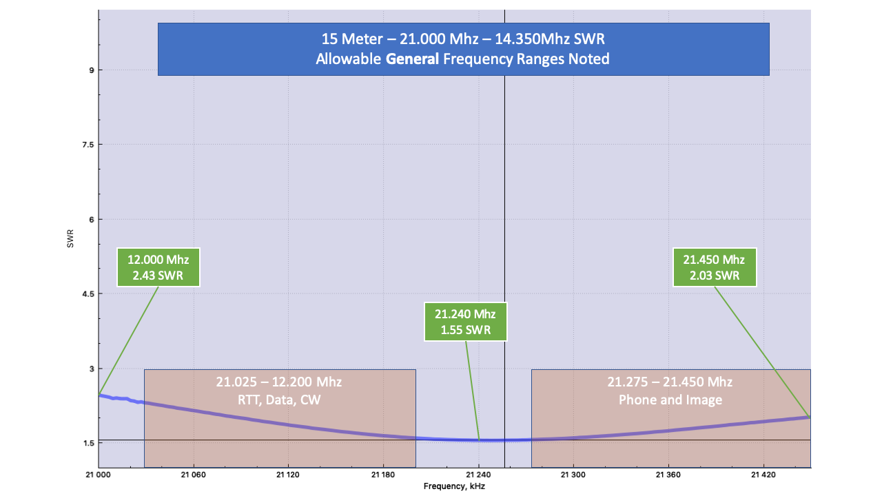
enter image description here For the 15 meter band I was surprised to see this range but it looks very good. Since 15 meter is really a harmonic of the 40 meter band it goes along for the ride.
Is the tuning for 15 meter primarily tied to the 40 meter dipole, or, is it more spread out amongst all dipoles?
For antenna shortening, what are the pros and cons of shortening in terms of cutting versus folding back on itself and twisting? .

Thanks in advance for providing some insight on tuning the fan dipole.
$\endgroup$
6
  • 1
    $\begingroup$ If you don't mind, I took the liberty of inserting the drawing of your fan dipole from the PDF that you referenced. :-) $\endgroup$ Commented Apr 28, 2019 at 18:40
  • $\begingroup$ How long and what feedline are you using? The SWR on 15m is suspiciously low. Though a 40m dipole doesn't resonate in the 15m band (myth busted), modeling shows that coupling between this antenna's three wires provides some compensation when driven on 15m. $\endgroup$
    – Brian K1LI
    Commented Apr 28, 2019 at 20:51
  • $\begingroup$ @BrianK1LI Are you sure about that? A 40m folded dipole that I made from 300 ohm TV twinlead many years ago worked very well on 15m. I made a Collins 75 ohm coaxial 4:1 balun which was at the feedpoint. $\endgroup$ Commented Apr 28, 2019 at 21:53
  • 1
    $\begingroup$ @BrianK1LI The antenna is located about 80' above the ground at the 80m antenna. From there it is about another 50' to the house. I'm using LMR400 straight through. If you have some pointers on modeling I'm open to seeing what's available. I'm trying to get a better handle on HF, and the proper antenna ... this is my first HF antenna so lots of learning going on. I ran the SWR several times using an antenna analyzer and my transceiver internal antenna tuner seems to match the SWR reading. $\endgroup$
    – Hogstrom
    Commented Apr 28, 2019 at 22:26
  • 1
    $\begingroup$ @Hogstrom Adding your transmission line to the model brings the SWR to reasonable agreement with your measurements on 15 meters. This model was EZNEC (NEC-2 engine). I also use 4NEC2 (free), depending on task needs. $\endgroup$
    – Brian K1LI
    Commented Apr 29, 2019 at 0:27

1 Answer 1

7
$\begingroup$

Before getting to the questions you asked, an observation: the design doesn't appear to include a balun. Adding one is probably a good idea.

Is there a way to flatten the SWR in this range [80m] or is this graph typical?

It's typical. Because 80 meters is such a low frequency, the fractional bandwidth of the entire band is quite large. For this reason sometimes the upper portion of the band is called "75 meters".

Getting a flatter SWR would require making the antenna fatter, perhaps by adding more wires to the fan at an appropriate length for 80 meters. But since an 80 meter dipole is already quite large, few people bother. An antenna tuner is probably a more practical solution.

Is shortening the antenna the proper way to shift the SWR to the right?

Yes.

Given the lower SWR is to the left of my target shortening the antenna seems to be the means to shift the SWR to the right, correct?

Yes.

Is the tuning for 15 meter primarily tied to the 40 meter dipole, or, is it more spread out amongst all dipoles?

It is mostly tied to the 40 meter dipole, but on any fan dipole the elements do interact to some extent, so it can be a good idea to recheck the tuning on all bands periodically. The particular design you have has the elements separated at the center and the ends, which is good because it should mean their interaction is quite low.

For antenna shortening, what are the pros and cons of shortening in terms of cutting versus folding back on itself and twisting?

Electrically, either method is identical. You can't uncut a wire obviously, so it would be prudent to keep a little extra length available.

$\endgroup$

You must log in to answer this question.

Not the answer you're looking for? Browse other questions tagged .