44
$\begingroup$

I am preparing to construct a resonant, center-fed, horizontal dipole. I have seen people use baluns at the feedpoint of the antenna, and some people swear by them, but I have never gotten a satisfactory answer on why you would use/need a balun. All the resonant dipole antennas I have made previously seemed to function just fine when used with 50 Ω coax and no balun. This consisted of connecting one leg of the dipole to the center conductor, and the other leg to the coax shield.

I do know that the normal impedance of a center-fed dipole at resonance is about 75 Ω, so I can see that there would be an impedance matching benefit of a balun.

What benefits (and/or drawbacks) does a balun provide in a resonant dipole antenna?

$\endgroup$
1
  • 5
    $\begingroup$ I want to note that because this is a good question, with good answers, and I like to link to it, that this problem is applicable to just about any antenna, not just dipoles. That includes verticals and loops. $\endgroup$ Commented Feb 26, 2014 at 17:25

7 Answers 7

48
$\begingroup$

Well, the canonical answer is that the balun converts the dipole (BAlanced) to coax (UNbalanced). But what does that mean?

For transmission lines (twin-lead or coax) to not radiate, each conductor must carry equal and opposite currents. It's these equal and opposite currents canceling each other that results in zero net field away from the transmission line. If the currents are not equal and opposite, then they don't cancel, and the difference results in an external electromagnetic field, and your transmission line radiates like an antenna.

This is generally undesirable. When transmitting, it can mean high RF in the shack, messing with speakers, digital electronics, etc. If attached to a directional antenna, it causes problems transmitting and receiving because the actual radiation pattern is a combination of the intended antenna, and the unintentional antenna formed by the feedline, which probably isn't directional at all. If you've modeled your antenna, the model assumes a feedline that does not radiate.

OK fine, you need equal and opposite currents in coax to make it not radiate. If you attach it to a dipole, you should get that. It looks pretty symmetrical, right?

Well yes, the dipole is symmetrical, but the coax isn't. Usually, the shield is attached to ground somewhere. Even if it isn't, the geometry of the shield and the center conductor are not identical, so the shield will have a different impedance with respect to the dipole than the center conductor.

Regardless of the coax, the dipole may not be really symmetrical anyway. Consider not just the antenna, but everything in its near field. Is it perfectly level to the ground? Is one end closer to a metal gutter?

The result of all these asymmetries is that each side of the dipole presents different impedances to the feedpoint. Ideally, the antenna would accept all the power sent to it by the transmitter. The equal and opposite currents put into the coax by the transmitter each go down opposite legs of the dipole where the EM energy is radiated away. But when the dipole is not balanced, the currents accepted by each leg of the dipole can't be equal. But, all the current must go somewhere, so the difference in current between the dipole legs is reflected back down the coax, back at the transmitter. (Note, this is distinct from reflection from impedance mismatches that causes high SWR.) However, this current doesn't have an equal and opposite current on the center conductor, so it radiates off the coax, like an antenna.

If you operate a dipole fed with coax without a balun, this is happening to you, though you may not notice. The coax shield radiates just fine, and if your signal still finds its way to the other station and you don't give yourself RF burns, then there's no problem. A good RF ground at the feedline's entrance to the shack can reduce the RF re-entry. Even without any special attention to grounding, at 100W, the RF in the shack probably won't do more than make some speakers buzz, which might be considered "normal".

By adding a balun, you are avoiding this issue. By isolating the feedline, you won't get RF in the shack, and your dipole will behave like a dipole described in textbooks. Your antenna tuning and performance won't be altered by other objects near the coax, because the coax won't be part of the antenna. If your dipole is in a good location for an antenna and your coax isn't, then you will have overall a better antenna.

$\endgroup$
2
  • 1
    $\begingroup$ Concentrating on coax and "unbalanced" transmission line confuses things. The real issue is common mode currents. Those can be carried just as easily on open-wire "balanced" transmission line. If you look at the wiring for toroidal baluns, they are balanced devices, all the way through. The benefit is choking the common mode currents. $\endgroup$ Commented Nov 12, 2013 at 5:56
  • 2
    $\begingroup$ @WalterUnderwoodK6WRU It's quite simple to make a dipole that's balanced enough with twin-lead and no balun. It requires some care, sure. It's not possible to make a dipole that's even remotely balanced with a coax feed, and that's the situation the question asked about, and that's what most people actually do. If you want to ask another question about common-mode currents feel free, but this answer is already over a page long. It can't explain everything. $\endgroup$ Commented Nov 12, 2013 at 11:59
22
$\begingroup$

A dipole is a particular machine for creating EM fields. The idea is to set up a voltage between the two halves of the dipole in such a way that an EM field is created and efficiently radiated away.

Remember, voltage is a difference between two things. When we consider just an dipole, with no feedline or anything else around it, it's very simple to see that the dipole is symmetrical. The currents in one leg create voltages against the other leg, because there's nothing else.

If we feed the dipole with twin-lead, it's still easy to see how the dipole can be symmetrical. Each leg is now working against the feedline, but since both leads of the feedline are very close to each other, they are affected equally by whatever the antenna is doing, and there is no net effect. Of course, everything else (the Earth, trees, gutters, towers, etc) around the antenna would also need to be symmetrical, and this is unrealistic.

If we feed the dipole with coax, the situation is very different. The shield intercepts any EM fields, effectively hiding the center conductor from any external fields. You don't have a symmetrical arrangement anymore: one leg of the dipole is connected to the shield, so really, it's an L shape. In fact, the shield is just as much part of the antenna as the dipole it's intended to feed.
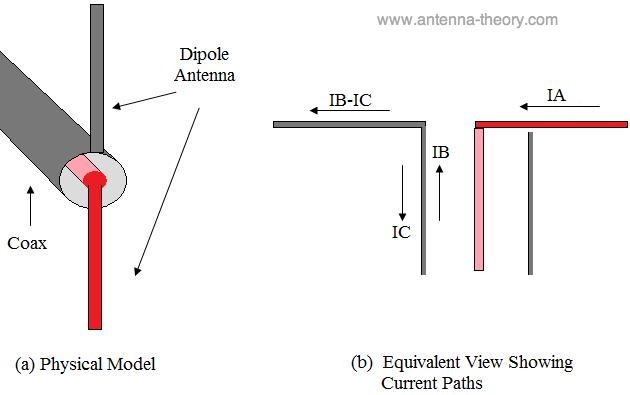
physical model of coax-fed dipole

from an excellent article at antenna-theory.com

So now consider what happens to the currents traveling down the coax. The signal from the transmitter consists of $I_A$ and an equal and opposite $I_B$. $I_A$ must flow down one leg of the dipole, because it has nowhere else to go. However, at the feedpoint, $I_B$ has two options: it can flow down the attached leg of the dipole, or it can reflect back down the coax shield.

Thus, $I_B$ will split, with some of it ($I_C$) returning on the coax, and the difference ($I_B-I_C$) going down the dipole, as intended. The degree of the split will be determined by the relative impedances of these two options.

This isn't often a problem, because the coax shield makes just as fine of an antenna as the dipole. It distorts the radiation pattern horribly, but since a dipole wasn't a directional antenna to begin, it hardly matters. It could mean that you get a lot of RF in the shack, but if you are transmitting with 100W this is unlikely to cause any serious problems.

There are however, some more subtle problems: if you are transmitting RF in the shack, you are also receiving RF from the shack (reciprocity). You might be able to get your antenna far away from the powerlines, switching power supplies, computers, and other noise sources in the shack, but if your feedline is actually part of the antenna, then you are receiving all this noise anyway.

By employing a balun, you are somehow forcing the currents on each leg of the dipole to be equal, so that no current returns on the coax, so that the coax does not radiate and act as part of the antenna. There are many designs, but one of the most common and effective is a simple common mode choke, also known as a 1:1 current balun. This clever device has the effect of inserting a large impedance between the feedpoint and the outside of the shield ($I_B$ and $I_C$ in image above), making it relatively more appealing for the current to go down the dipole:
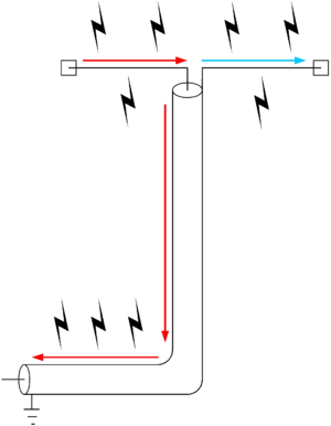
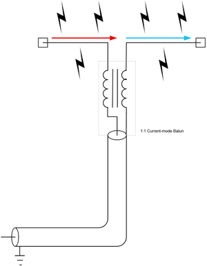
dipole without balun dipole with balun

from Wikipedia

Note that the mismatch of 50Ω coax to a 75Ω antenna isn't relevant to any of this. If your feedline and antenna are mismatched, you will get some power reflections, but those reflections would be inside the feedline, and not cause the feedline to become part of the antenna. There are balun designs that also perform impedance transformation, but this is not the function denoted by balun. On a practical note, 75Ω is a good enough match to 50Ω, and typical feedline losses at HF low enough, that in my opinion most attempts at impedance matching in this situation are unnecessary, and likely waste more energy through inefficiencies than they gain in obtaining a better match.

$\endgroup$
6
  • $\begingroup$ This is misleading, because it assumes an ideal dipole and because it suggests that balanced transmission line forces balance in an antenna. The latter is just wrong, and the former is false for nearly all real antennas. An antenna is balanced when the impedances of the two elements are equal. Period. The surroundings of an antenna almost always make them unequal and thus make the antenna unbalanced. You could trim the elements to make them more equal, but then it would rain or a bird would land on one end. That is why we use baluns. $\endgroup$ Commented Nov 12, 2013 at 6:03
  • 2
    $\begingroup$ @WalterUnderwoodK6WRU You aren't wrong...what I meant to say is that with a balanced feeder it's at least possible in theory to make a balanced dipole, while with a coax feeder you are guaranteed to have very poor balance. Can you tell me what specifically in the answer could be improved? $\endgroup$ Commented Dec 22, 2014 at 14:51
  • $\begingroup$ The article at antenna-theory.com seems to be correct, but it is very confusing. That, and this answer, imply that coax is "unbalanced". That term makes sense at audio, but not at RF. Coax is balanced. But...it is a three-conductor system. There are balanced currents on the outside of the inner conductor and the inside of the outer conductor. Physics ensures this. Common-mode currents flow on the outside of the outer conductor. Baluns reduce common-mode currents from unbalanced antennas, but other sources may induce currents in the outside of the shield. $\endgroup$ Commented Dec 23, 2014 at 16:44
  • $\begingroup$ @WalterUnderwoodK6WRU I think you are conflating an unbalanced line, which means unequal impedances to ground, with unbalanced currents, meaning common-mode currents. $\endgroup$ Commented Dec 23, 2014 at 21:23
  • 1
    $\begingroup$ You say Ia must go into the dipole, while some of Ib can reflect back instead. Why can't Ia reflect too? $\endgroup$ Commented Nov 20, 2015 at 7:40
10
$\begingroup$

Another answer mentions the paper by K9YC, Jim Brown. This is the best reference on baluns in amateur radio. See: http://audiosystemsgroup.com/RFI-Ham.pdf

Chapter 6 is about baluns and antennas. He says, "The primary function of most baluns, at least in our ham stations, is to minimize the interaction of our antennas with the transmission lines that connect them to our radios."

The interactions we are minimizing are two, "RF in the shack" and common-mode noise.

Real antennas are unbalanced by their surroundings: trees, buildings, ground conductivity, and so on. This causes unequal impedances presented to the two terminals of the transmission line and problems with RF going other places. Any imbalance turns into a common-mode voltage on both conductors of the transmission line. This can radiate and cause problems with transmitted RF in your radios and in other electronic devices in your home and your neighbors'.

Common-mode signals can also be received. Nearly all nearby noise sources will be picked up equally by the two elements (and the transmission line) and show up at the radio summed with the desired signal.

A current balun (the only kind you want) will present a high impedance to common-mode signals and a low impedance to differential signals. If the two are 5000Ω and 50Ω, that is a 100X attenuation of the common-mode signals.

I have a dipole at about 30', strung between two trees and over our house. The house has a steel beam just off-center under the dipole. This is obviously unbalanced, even though the elements (separate for 40m and 20m) are equal length. Adding a balun dropped the received noise by about 6dB.

Drawbacks of a balun? Cost and attenuation. My balun (from Balun Designs) cost $55, a significant addition to the cost of a wire antenna. A well-designed toroidal balun will have an insertion loss of 0.1db (see http://www.balundesigns.com/servlet/the-58/QRP-1-cln-1-baluns-balun/Detail). A balun made from coiled coax may have significant attenuation due to the amount of coax.

I strongly recommend reading chapter 6 of K9YC's paper.

$\endgroup$
0
$\begingroup$

A so-called "current balun" consists of a bunch of ferrite cores with the coaxial feed line running through their centers. This greatly reduces RF current flow on the outside of the shield, which, in turn, reduces RF losses. It doesn't affect the impedance mismatch, but that's minor.

$\endgroup$
2
  • $\begingroup$ You can build a current balun/choke with a lot of ferrite cores on the coax (as you describe), or with a coil of coax, or with a toroidal transformer. $\endgroup$ Commented Nov 5, 2013 at 15:41
  • $\begingroup$ @WalterUnderwoodK6WRU - yes, thanks. The one I did uses ferrite cores. $\endgroup$
    – Pete NU9W
    Commented Nov 5, 2013 at 16:09
0
$\begingroup$

Phil did a good job of explaining what is going with the currents at work.

As to the why you need to care, weel, as you note in the question, the feedpoint impedence is 75Ω and you are feeding it with 50Ω coax. If the currents are not perfectly balanced, some of that RF is going to see that feedline as a lower impedence path and use it.

Will it still work? Yep, no problem. Feed line radiation will affect the pattern of the antenna, but let's be honest here, a dipole not directional anyway, so you almost certainly won't notice.

The RF coming back may or may not matter. It depends on the power level you are using and the frequency. If you are running QRP on 80m, no issue. If you are cranking 1500w, at almost any frequency, now you have a problem.

The solution is to add impedence to the outside of the coax sufficent to convince the RF to stay in the antenna. How impedence depends on who you ask? I have seen references state as little as 500Ω to be sufficent (ARRL Handbook), others say 1000Ω (W1HIS) and have read a long and compelling paper that states that the goal should be 5000Ω (K9YC).

Note that the impedence presented by ferrite cores varys with frequency (and temperature). the two main variables in selecting ferrite are form factor and "mix" (what they are made of). You need to select ones targeted to your operating range (typically mix 43 or 31) and large enough to handle the power without heating up too much. All ferrite has a magic temperature once crossed, the impedence drops to nothing but the resistence goes UP resulting in a thermal runnaway that melts your coax.

$\endgroup$
1
  • 1
    $\begingroup$ I think this is really wrong. An impedance mismatch will cause power to be reflected at the mismatch (in this case, the feedpoint), but this is not related to common-mode currents. A perfectly balanced antenna that is mismatched will still have reflected power, and a perfectly matched antenna can have common-mode current. $\endgroup$ Commented Dec 30, 2013 at 12:14
0
$\begingroup$

All great answers, Most rfi is caused by severely mismatched antennas subjected to high power. I agree that a 1 to 1 balun will help in certain dipole installations close to ground or when coax feedline is configured in a non symetrical layout when departing the antenna. A 1 to 1 balun does not affect the matching, 75 to 50 ohms or whatever, not what it is designed for.

I do not use a balun on any of my various wire beams and would seriously consider the center weight added by a balun and the cost vs most non problems on simple dipoles at 1/4wl and higher will show that the addition of a current balun is not needed.

$\endgroup$
0
$\begingroup$

For SWL reception, I have never used a balun. It could in fact reduce unwanted RF, but even random turns of coax can produce enough positive results on receive-only usage. For transmitting, it is obviously a completely different scenario, and I always use 1:1 baluns on half-wave dipoles and Yagis.

$\endgroup$

You must log in to answer this question.

Not the answer you're looking for? Browse other questions tagged .