4
$\begingroup$

Is spacing of parallel dipoles necessary. Could they be banded together and then trimmed or is there some consideration, other than tuning, requiring separation.

I was considering a fan dipole. I have seen one where 300 ohm twin lead was used for two dipoles and I believe a 2nd piece for another 2 dipoles, all fed from a single line. I haven't seen one of those in use but assuming it worked (it's in the antenna bk) the spacing is about 1/2".

$\endgroup$
6
  • 2
    $\begingroup$ Hello Mike, and welcome to ham.stackexchange.com! $\endgroup$
    – rclocher3
    Commented Jan 26, 2021 at 18:25
  • 4
    $\begingroup$ Are you asking about a fan dipole, cage dipole, or two separately fed dipoles (phased array, or multi-op station, etc.)? $\endgroup$
    – hotpaw2
    Commented Jan 26, 2021 at 18:34
  • 2
    $\begingroup$ Hard to say what's necessary if you don't specify what the objectives are. Please edit the question to clarify. $\endgroup$ Commented Jan 26, 2021 at 22:23
  • 2
    $\begingroup$ @mikezias please edit the question to clarify. $\endgroup$ Commented Jan 27, 2021 at 15:41
  • 2
    $\begingroup$ @mikezias if you can additionally include pictures, screenshots, links etc to the antennas you've seen that's even better. $\endgroup$ Commented Jan 27, 2021 at 15:42

5 Answers 5

3
$\begingroup$

Spacing is absolutely required between the antennas.

You cannot bundle all the wires together. They must be spaced apart, or the interaction between them will be too great. You'll have a mostly useless "multiband" antenna.

Some of these search results indicate the need for spacing, as does this question.

$\endgroup$
3
$\begingroup$

In my experience no need for any spacing at all. I've made 80-10m fan dipoles with ribbon cable. Yes, the wires interact but after tuning I got nice clean resonances on all bands. Start with the shortest wavelength first and work down.

Just my $0.02.

$\endgroup$
2
  • $\begingroup$ Well, that is interesting. I once made a fan type dipole but with spacing of several inches. Currently I am thinking of using a ZS6BKW variant of the G5RV. I may try a couple of dipoles with minimum, if any, spacing and trim per your suggestion. Other than the twin lead type I have not seen any close spaced designs, however I have not seen any experimental evidence to show bundling cannot be done. $\endgroup$
    – mike zias
    Commented Feb 3, 2021 at 20:45
  • $\begingroup$ As Glenn's answer nicely points out, ribbon cable will have a power limit because of the likelihood of arcing through the insulation. But I believe you, even though it contradicts my "you can't" answer. $\endgroup$ Commented Feb 4, 2021 at 19:21
2
$\begingroup$

You don't say if you're talking about several dipoles connected together into a single antenna, which is an arrangement usually called a fan dipole, or several nearby dipole antennas that each have separate feed lines.

If you consider a piece of metal up in the air near a transmitting antenna, it is not difficult to imagine that the metal absorbs some of the RF from the antenna, which induces currents in the metal, which cause the piece of metal to re-radiate RF at the same frequency. The radiation pattern from the piece of metal interferes with the radiation pattern from the antenna, constructively in some directions (more gain) and destructively in others (less gain). So if the piece of metal is close enough to the antenna to absorb a meaningful amount of energy from the antenna, then one can see that the radiation pattern and impedance of the antenna are affected. That's how a yagi antenna works; a yagi is just a dipole (the "driven element") with a few metal rods ("passive elements") cleverly placed near it in a way that enhances gain in one direction. The same principles work in reverse for receiving, so if an antenna has more gain when transmitting in a certain direction, then it typically will have more gain receiving from that direction also. (There are exceptions.)

So a fan dipole is a bunch of dipoles cut for different frequencies that are strung near each other, and connected at the middle. (If you were to tightly band the dipoles together they would mostly act like a single dipole made with the longest wire, and not like a multi-band antenna. The wires in a fan dipole are typically held some distance apart by spacers.) Fan dipoles work, but if you were to build one by making several individual dipoles and then connecting them together, then you would find that the impedance and radiation pattern at one of the old resonant frequencies has changed quite a bit. They typically need careful adjustment of the lengths of all the wires, and the spacing between the wires, to have low SWR at the right frequencies. That's one of the main drawbacks of fan dipoles, that they need lots of careful tweaking to work well.

If you were talking about several dipoles with individual feed lines near each other, then similar considerations apply. The closer the antennas are together, the more they will interact with each other. (I've heard several closely-spaced antennas described as "a single antenna with multiple feed ports".) The more they interact, the more the radiation patterns and impedances will change, and the more they will need to be tweaked to work well together.
$\endgroup$
3
  • 1
    $\begingroup$ Is there any experimental (or simulated) data to show the effects. I don't have one of the analysis programs. $\endgroup$
    – mike zias
    Commented Jan 27, 2021 at 0:28
  • 1
    $\begingroup$ 4nec2 is free software. You could fiddle with a model of a fan dipole, but it wouldn't be accurate enough that you could make a model and then just build the real antenna with the same dimensions and have the SWR be 1:1. Unfortunately there's no substitute for "cutting" the antenna wire and then measuring the SWR on each band. You don't actually need to cut the antenna wire; if you fold it back on itself and hold it with a zip tie, then electrically that's the same as cutting it, but you can cut the zip tie and unfold the wire to make it longer if necessary. $\endgroup$
    – rclocher3
    Commented Jan 27, 2021 at 1:04
  • 2
    $\begingroup$ There are lots of articles and YouTube videos about making fan dipoles. There are also lots of other multi-band wire antenna designs out there. $\endgroup$
    – rclocher3
    Commented Jan 27, 2021 at 1:08
1
$\begingroup$

Consider this "mind experiment" for a limiting factor in the separation required for "Fan Dipole Radiators".

  • Given a Fan-Dipole for 28MHz and 4MHz.
  • Given a Effective Power Out of 1KW, from a tube amp of 1000 V Plate Voltage.
  • Given a distance between radiators of 0.5 inch.
  • Given that the peak voltage (RF) may reach 3KV.
  • Given that the 28MHz Voltage Lobe is located 0.5 inch away from the 4MHz Current Lobe .
  • Question: Will the 28MHz Voltage Lobe arc from one bare wire to another, through air , to the 4MHz Current Lobe ?
  • Question: Will there be "de-Tuning" in this extreme example ?
  • The previously supplied "answers" and "cautionary methods" are a good faith effort in managing any "De-Tuning" that may arise.
  • My method has been to use 5 inch spacers, and 'stack" the dipoles progressively ( 80,40,20,15,10M , side by side.) such that Voltage Lobes are as separated as much as they can be.
$\endgroup$
1
$\begingroup$

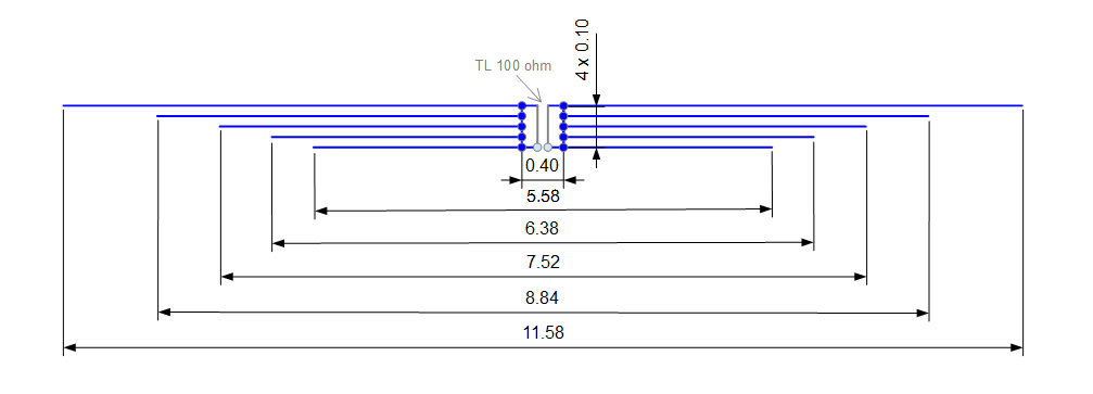
Spacing of parallel dipoles influences the bandwidth you can achieve on every particular band. The smaller the spacing, the more narrowband antenna becomes. However, there is a trick you can use to achieve a little larger bandwidth while not spacing the dipoles too much. See my website here.

The trick is to use a configuration I call a split feed point.

$\endgroup$
8
  • 1
    $\begingroup$ Welcome to StackOverflow! Please describe the trick in your answer here rather than just pointing off to your site. If your host changes its linking scheme, a broken link will quickly frustrate people who want to know more. $\endgroup$ Commented Apr 17, 2021 at 8:57
  • 1
    $\begingroup$ The trick is difficult to explain without a drawing. So, I will add a picture to my initial answer. $\endgroup$ Commented Apr 17, 2021 at 10:07
  • $\begingroup$ That is very interesting - I have not seen that method of feeding dipoles before. Another method I have though of is to use a remote switch to put resistors in the dipoles not being used. This, I think, would add enough impedance that they would not accept power and detune the operational dipole. Well, at present I am considering a flag pole antenna, at much greater expense, as my HOA (that would be my wife) doesn't want the wires over the yard but will accept a flag pole. I still may experiment with the dipole, however, just not a permanent fixture. I will look at your postings. $\endgroup$
    – mike zias
    Commented Apr 17, 2021 at 20:24
  • $\begingroup$ I don't understand how those two 50 ohm coax pieces work. How long are they? And it appears that (1) the shields are only connected to each other, and (2) the center conductors are shorted by the other connections. $\endgroup$ Commented Apr 18, 2021 at 18:16
  • 1
    $\begingroup$ Two 50 ohm cable pieces form a shielded balanced transmission line of characteristic impedance 2x50=100 ohm. You may read about such lines in the latest ARRL Antenna Book, page 23.28, Figure 23.26. Its length is 40 cm. Although 40 cm may look not so much, it can not be approximated as a short circuit in the frequency range 14-30 MHz. You need to treat it as antenna element or as a complex LC circuit perhaps. We can generally say, that such a feeding method changes phase differences among the RF potentials in various segments of the antenna parallel wires. $\endgroup$ Commented Apr 19, 2021 at 11:17

You must log in to answer this question.

Not the answer you're looking for? Browse other questions tagged .