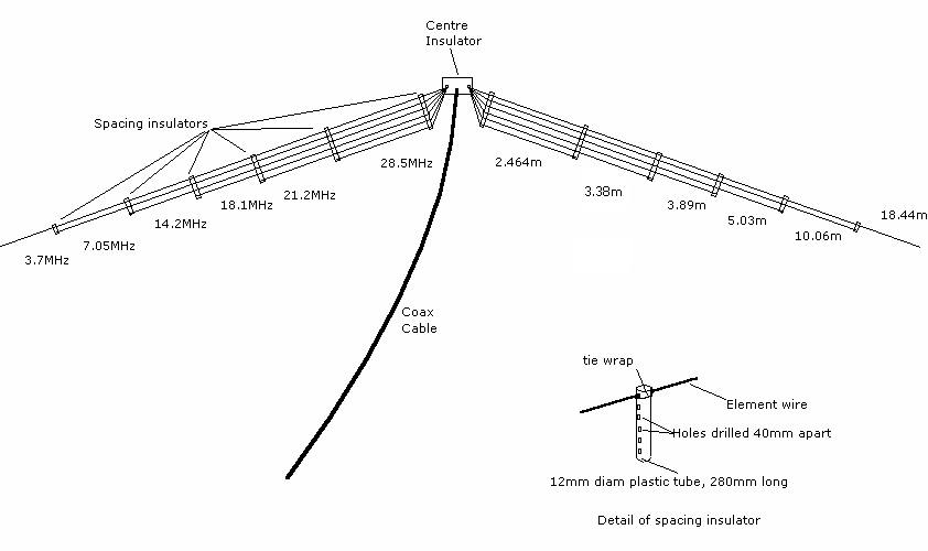
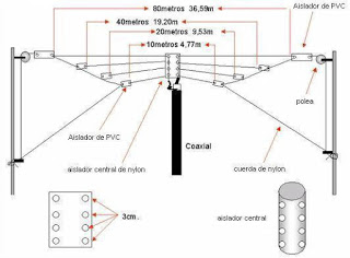
2
$\begingroup$

I plan to put up a "fan inverted vee" but for various reasons I will not be able to take it down, adjust wire lengths, put it up, test, etc: I will basically have to cut the wires, put it up and leave it up there. So given I sort of have one shot, I want to get the most accurate estimate by doing some modelling of my actual geometry, which I am able to do in the excellent EZNEC package. I note that I do have an antenna tuner (MFJ Intellituner).

But here is the problem: when I create such an antenna with the inverted vees from different bands physically far apart, I get a good result (low SWR in desired part of band), but when I create something that looks a lot more like the fan dipole/vee antennas you see described in numerous places, I see the shorter wavelength antenna having a swr like 10+. I expect this is the wrong answer.

It may be that I have done something wrong in creating the model in EZNEC. I took the two band case (40m/20m) and created the basic antenna by using a short (one foot) central wire on which I place the source. Then I have 40m and 20m wires coming out from the ends of the one foot section.

When the 40m section is a dipole (straight line) and the 20m section drops 35 degrees from each end, the swr looks very good for both bands (well under 2:1 in the desired band segments). But if I then drop the 40m wires by 30 degrees on each side (so they are close-ish to the 20m wires), the 40m swr looks fine but the 20m swr is in between 10 and infinity in the region of interest.

Being a beginner with EZNEC, I suspect it is me doing something wrong! Below I attach from EZNEC 1) the dipole configuration 2) the source set-up 3) the "fan inverted V" configuration and a diagram showing the antenna.

I note that I am using the "demo" version with a maximum of 20 elements. Might this be why the antenna seems to not "work" in EZNEC?

Thanks
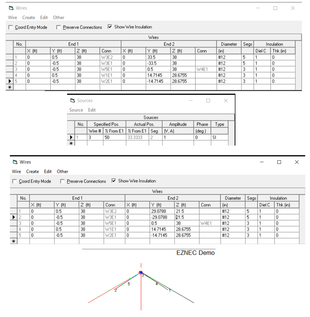
fan inv v puzzle

$\endgroup$
4
  • 1
    $\begingroup$ For that short 1-foot segment for applying your source exitation it is best to make its length the same as the other segment lengths of your antenna. For example, say you have a 10 foot long wire with 10 segments then each segment is 1 foot in length. In this case your short middle segment is OK. But, for other lengths and/or segment counts, make sure that the middle segment is the same length as the other segments in modeling your antenna. I am not sure if this is a the problem you have so I am not making this answer. $\endgroup$
    – K7PEH
    Commented May 17, 2020 at 20:38
  • 1
    $\begingroup$ Hello and welcome to ham.stackexchange.com! $\endgroup$
    – rclocher3
    Commented May 18, 2020 at 14:01
  • 3
    $\begingroup$ BTW, 4nec2 uses the exact same modeling engine as EZNEC, but is free and doesn't limit the user to 20 segments. $\endgroup$
    – rclocher3
    Commented May 18, 2020 at 14:06
  • 1
    $\begingroup$ Thanks for the helpful comments! I’m coming back to ham radio after 40yrs QRT - I forgot what a friendly and helpful bunch the ham community is. $\endgroup$ Commented May 18, 2020 at 20:06

2 Answers 2

5
$\begingroup$

Yes, being limited to 20 total segments for two dipoles is likely to be a problem, especially because of your hope / plan / expectation to have the model accurately predict what is built. I created an EZNEC model of a fan dipole for 40 and 20 meters; even the minimum segmentation - which, don't forget, must suffice at the highest operating frequency - required 21 total segments, which produced a somewhat different SWR curve than was obtained with more segments.

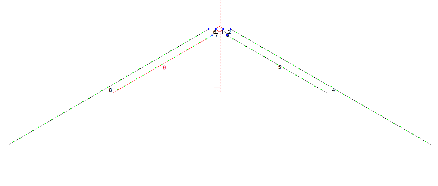
Feedpoint geometry, as mentioned by another poster, is critical when simulating a design where two pairs of wires are meant to meet at a single set of terminals. I modeled the antenna thus:

enter image description here

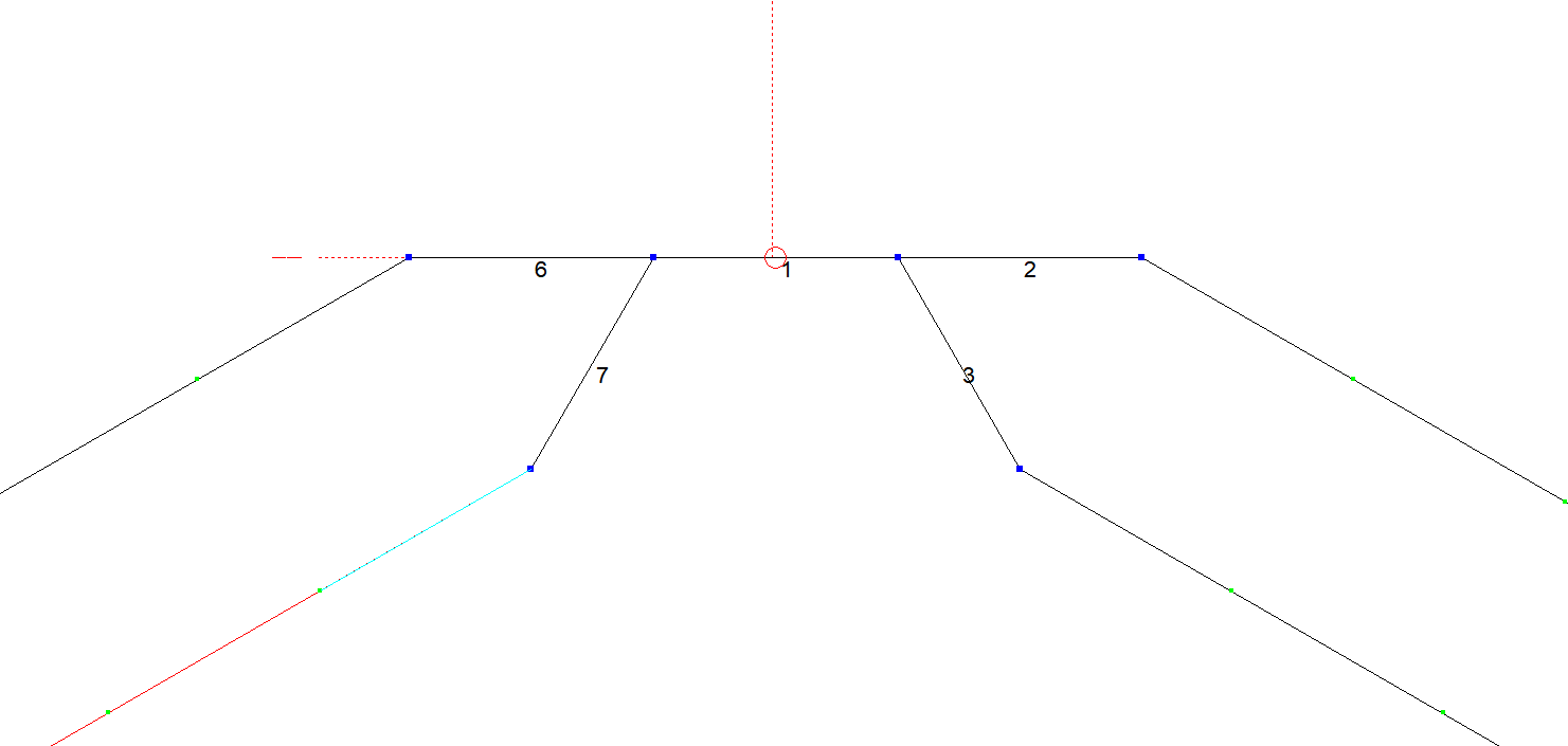
with this geometry at the feedpoint:

enter image description here

All segments are 1-ft long, for a total of 51 segments.

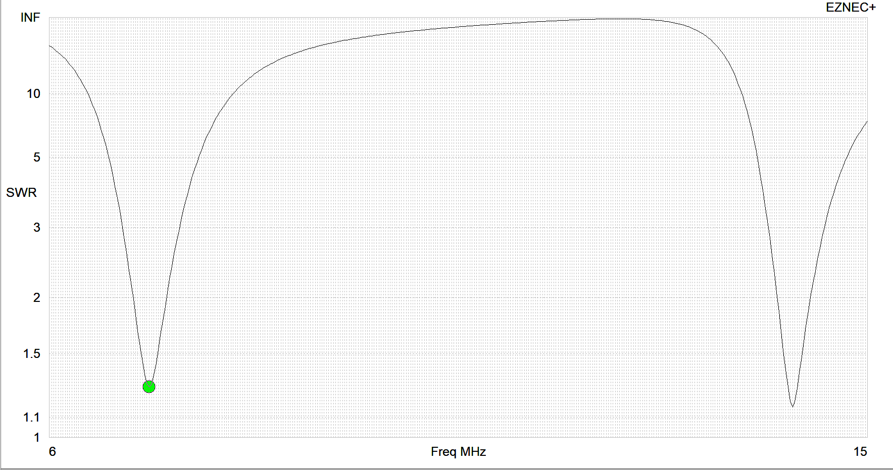
The resulting SWR curve, over medium-conductivity "Real" ground, is well behaved, with resonances at 7.1-MHz and 14.175-MHz:

enter image description here

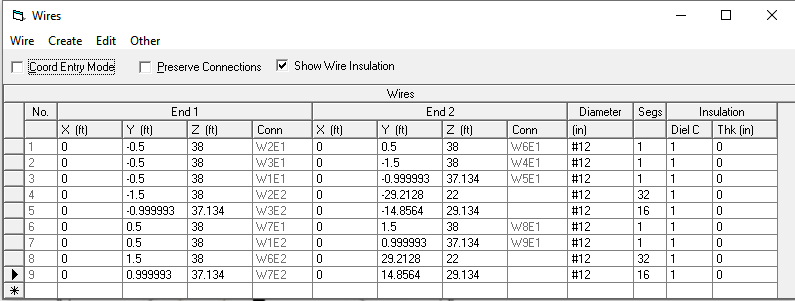
For your reference, here are the wire descriptions:

enter image description here

$\endgroup$
4
  • $\begingroup$ +1! What happens when you reduce the segments down to 20, Brian? In my experience, you will lose a little accuracy, but usually not enough to matter in the real world. $\endgroup$ Commented May 19, 2020 at 1:41
  • 1
    $\begingroup$ @MikeWaters Accuracy is precisely the point (yes, pun intended). The OP says he has "one shot" to get his design right, which is a tall order for a simulation, given all of the environmental vagaries. $\endgroup$
    – Brian K1LI
    Commented May 19, 2020 at 10:07
  • $\begingroup$ Brian many thanks for all the work you did there! I am being slightly lazy as I could do the trig, but what are the 20 and 40m lengths please? It’s interesting to see how different they come out compared with the standard dipole lengths for those frequencies. If you didn’t save the model no worries. And I guess the SWR is relative to a 50 ohm feeder? $\endgroup$ Commented May 19, 2020 at 18:20
  • 1
    $\begingroup$ @RiskyScientist No worries, it's a worthy question to address, Risky. The angles between the wires at the feedpoint are 60-degrees and the wires are tilted 30-degrees down from horizontal. This model seems to be sufficiently well-behaved to be believed, but no warranty is expressed or implied and your mileage may vary! $\endgroup$
    – Brian K1LI
    Commented May 19, 2020 at 18:53
2
$\begingroup$

I doubt that the segment limits of the program is your main problem. You should get accurate enough details in spite of that.

Part of the problem is at the feedpoint. You need to build your fan dipole so that there are insulating spreaders* to keep the wires for the different bands parallel and farther apart from each other for most of their length. As it is, the wires are too close together for most of their length, and thus they are interacting with each other too much.

Here's an easy solution: Add some short, steeply angled wires on each side --between the feedpoint insulator and the existing wires-- to get them away from each other. (Commercial multiband fan dipoles do this.) After that, you can adjust the length of each dipole to compensate for their interaction with each other.

Multiband dipole

This design has a spreader as the center insulator:

Fan dipole

*The spreaders could be rigid strips of plastic with holes drilled every 6 inches, and one should be as close to the feedpoint as practical.

The alternative would be to not worry about being parallel with each other, and greatly increase the angle between them. One example of this might be to have two dipoles 90° to each other, or three dipoles 60° apart. It's often better not to do it this way due to the directional pattern of dipoles, but that's another story.

(I once asked about the same thing here, but I can't find the question.)


Photo credits: First Second

TL;DR:

The wires are too close.

$\endgroup$
1
  • $\begingroup$ The 6" spacing was just a suggestion. One design uses a much closer spacing. $\endgroup$ Commented May 18, 2020 at 21:26

You must log in to answer this question.

Not the answer you're looking for? Browse other questions tagged .