8
$\begingroup$

Since I'm working with wireless communications, I decided it would be good to educate myself a little and at least get a basic understanding how does a Wi-Fi antenna work.

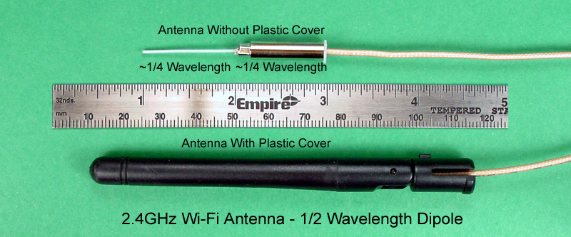
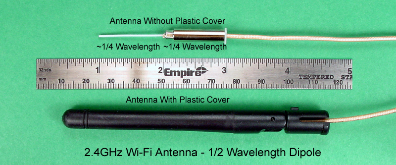
My first question is about the most basic 2.4Ghz antenna that is usually attached to every cheap Wi-Fi router you can find on the market. I stumbled upon this link, which happily explains that the such antenna is a half wave dipole and has a picture of it removed from plastic cover, which is copied below. Everything's fine so far, except it's hard to not see that the length of one half of the dipole on the picture is ~25mm, but 1/4 wavelength of 2.4Ghz wave is ~30mm. Does anyone know where does that difference come from?

photo of typical WiFi dipole antenna with plastic cover removed

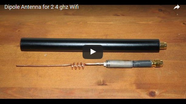
Next question is about high gain Wi-Fi antennas. I found a video showing internals of such antenna, and it turns out that the only difference is that one half of the dipole is longer and contains a coil. The author of the video says that it is a loading coil, and if I understand correctly they are used to shorten physical antenna length. But here the standard half-wave dipole was made longer. To summarize: How does making the antenna longer increases its gain? And why in this case only one half of the dipole was made longer?

Thanks in advance for explanation!
$\endgroup$
3
  • $\begingroup$ Welcome to ham.stackexchange.com! $\endgroup$
    – rclocher3
    Commented Feb 12, 2017 at 19:17
  • 1
    $\begingroup$ You really want to split these into two separate questions. It is best to have only a single question that way there can be a single matching answer for the format of Stack Exchange. $\endgroup$ Commented Feb 16, 2017 at 19:44
  • $\begingroup$ The 1/2 wave antenna is not a dipole. It is a monopole. 5/8 wave antennas are like that, too - those are the 14-inch antennas you'll see advertised in the usual places. $\endgroup$
    – SDsolar
    Commented May 13, 2017 at 0:09

3 Answers 3

4
$\begingroup$

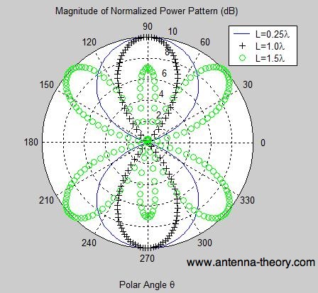
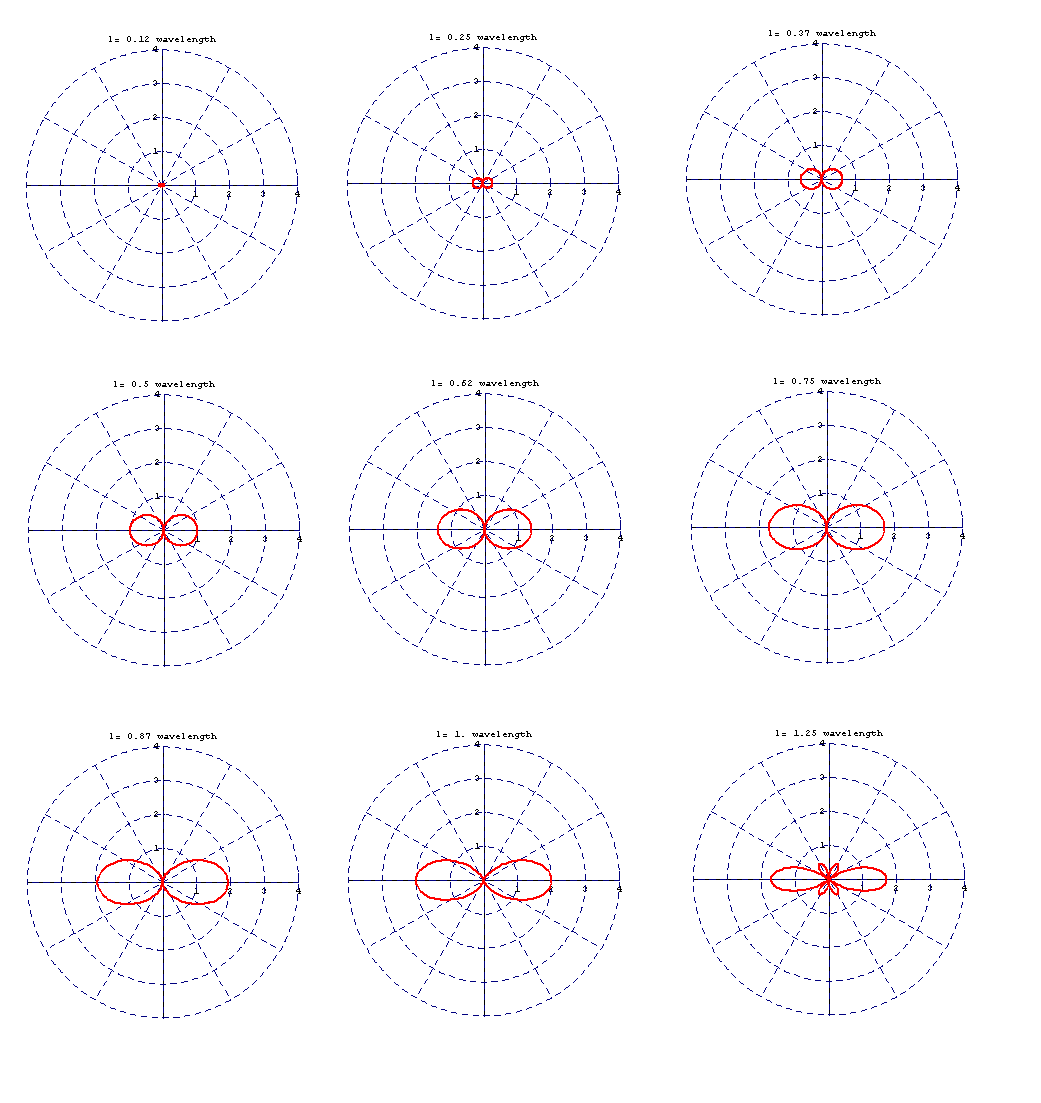
Between lengths of infinitesimal and one wavelength, the lobes in the radiation pattern become narrower. Here's a picture from antenna-theory.com:

enter image description here

Notice how for the 1-wavelength antenna, the lobes are skinnier than the 0.25-wavelength antenna. A 0.5-wavelength antenna is somewhere between the two. These patterns can be calculated from the current distribution on the dipole. The math isn't simple so refer to antenna-theory.com if you want the math.

Assuming antennas with negligible losses (which these are), it's a fact that as the antenna pattern becomes narrower, gain in the peak direction increases. Gain can't increase in all directions because that would violate the law of conservation of energy.

As the dipole becomes longer than 1 wavelength, the pattern starts growing extra lobes which aren't pointing in any useful direction. The maximum gain peaks around 1.25 wavelengths (see 5/8 wavelength monopoles). Beyond that the lobes continue to get narrower, but also more numerous so peak gain does not increase.

So that explains why the higher gain antenna is longer, but why the coil? When a dipole is (approximately) a half-wavelength long, it's resonant and has a feedpoint impedance in the neighborhood of 75 ohms. This is a good match for most transceivers, so the antenna can be connected directly to the radio.

At different lengths, the dipole itself is no longer resonant and the feedpoint impedance will be something else. As such, some additional impedance matching will be required to efficiently couple the antenna to the radio, and that's what the coil does.

$\endgroup$
1
  • $\begingroup$ Thanks for this explanation and very useful links. I've started reading them, and it turns out that part of the theory on this site (high frequency transmission lines) was a subject on my univerity course, but not in context of antennas. I'll continue reading the site :) $\endgroup$
    – xba
    Commented Feb 13, 2017 at 21:02
4
$\begingroup$

This is the 2nd antenna of the question (screenshot from video linked in the question).

enter image description here

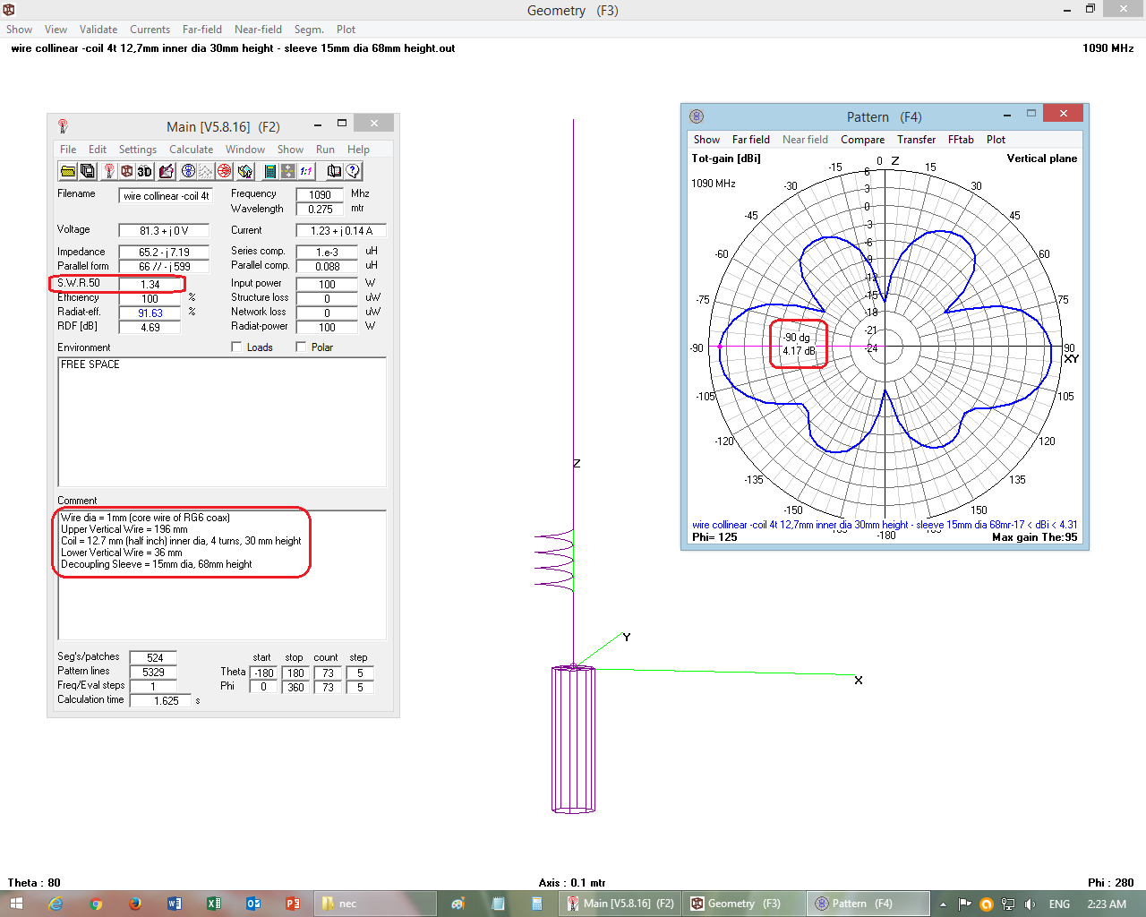
Below are simulation results of an antenna similar to the one above. Although simulated antenna is not for WiFi 2.4 GHz (it is for ADS-B, 1.090 GHz), this simulation gives a general idea of characteristics of this type of antennas.

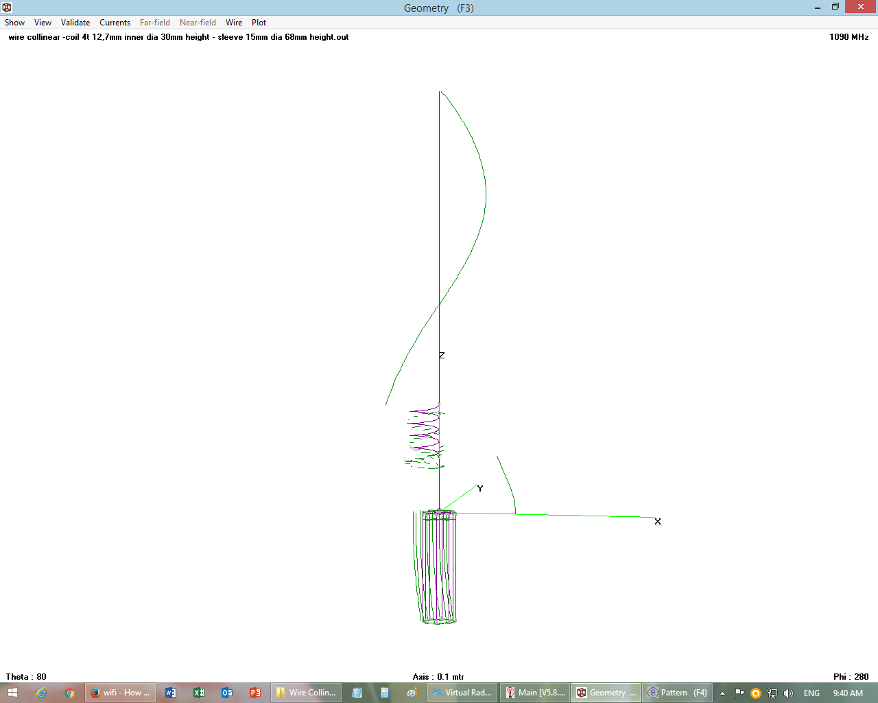
The simulated antenna has two vertical sections, a coil and decoupling sleeve. Upper vertical wire is slightly longer than 5/8 λ. while lower vertical is slightly longer than 1/8 λ. The coil between two vertical section is used for phase-shifting the currents, as well as impedance matching. The decoupling sleeve is 1/4 λ in length.

CLICK ON IMAGES BELOW TO SEE FULL SIZE
.
.
Image 1 of 2 - Gain, SWR, Radiation Pattern
Wire collinear antenna with decoupling sleeve .
.
.
Image 2 of 2 - Current Distribution
Current Distribution

$\endgroup$
2
  • $\begingroup$ Thanks! These are great pictures and actually the only pictures of such antenna I've found. So this is a collinear anteanna then? I have a couple of questions? $\endgroup$
    – xba
    Commented Feb 13, 2017 at 20:40
  • $\begingroup$ And here are my questions, since apparently this site does not allow you to edit the comments after more than 5 minutes from posting: - you called the bottom part of this antenna a "decoupling sleeve". Is there a reson why it is shaped like that? Wouldn't it be cheaper for the manufacturer to simply put a piece of wire instead of the sleeve? - the currents on the sleeve and top part of this antenna seem to be out of phase and the amplitude of the former is much bigger. Do you know what is the advantage of such setup? $\endgroup$
    – xba
    Commented Feb 13, 2017 at 20:47
4
$\begingroup$

The antenna in photo below is the 1st antenna of the question.

Wi-Fi 2.4GHz 0.5 Wavelength Dipole

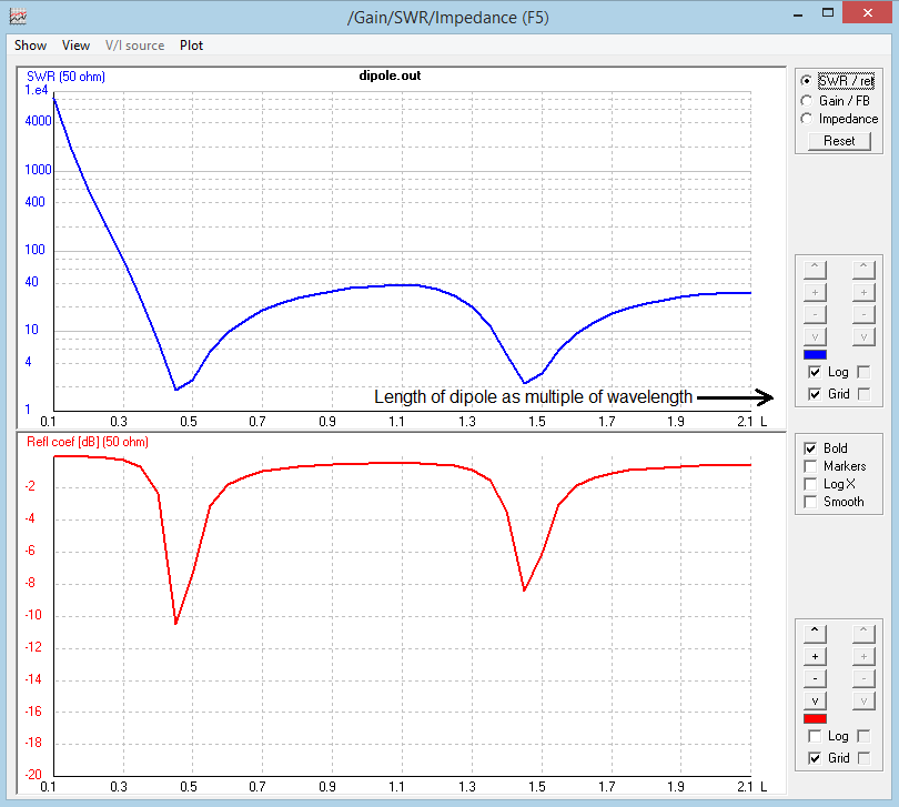
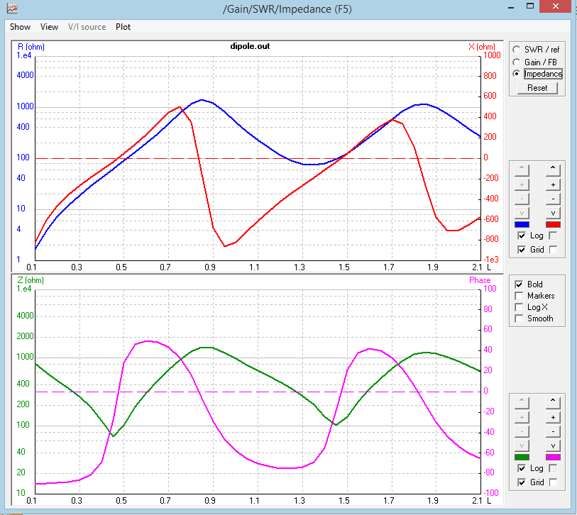
It is supposed to be 1/2λ long (radiator+sleeve). However its length is 2x25 mm instead of 2x30 mm. The antenna will still work even if its length is different from 1/2λ. However the impedance/swr of antenna changes as the length changes. When dipole's length is exactly 1/2λ, its impedance is 75 ohms.

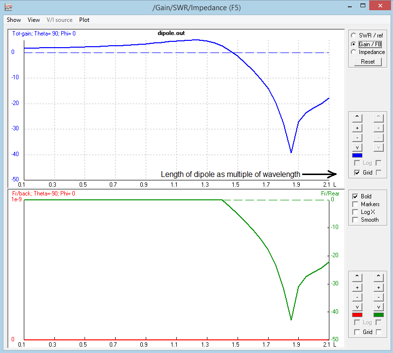
Please see sketch below which shows Gain & Radiation pattern for dipoles of lengths from 0.12λ to 1.25λ (total of both limbs):

CLICK ON IMAGES BELOW TO SEE LARGER SIZE

Dipole length vs radiation pattern

Dipole SWR vs Length (0.1λ ~ 2.1λ)
dipole swr vs length

Dipole Gain vs Length (0.1λ ~ 2.1λ)
dipole gain vs length

Dipole Impedance vs Length (0.1λ ~ 2.1λ) dipole impedance vs length

$\endgroup$
2
  • 1
    $\begingroup$ Thanks for this explanation :) I was trying to find the specific reason why it's 2.5cm. I know that by making a half-wave dipole slightly shorter, reactance can be reduced to 0 and the antenna will be in resonance. But every site I found says that the typical "shortening factor" is 0.47-0.48λ. That still gives about 2.8cm for one part of the dipole for 2.4Ghz, but I have found many antennas like this on the Internet with precisely 2.5cm length. I guess there must be some other reason behind that then? $\endgroup$
    – xba
    Commented Feb 13, 2017 at 20:58
  • 2
    $\begingroup$ @xba - If you look at the "swr vs length of dipole" plot, the minimum swr is at 0.45λ = 0.45 x 120 mm =54 mm, which makes each limb 54/2=27mm. Since the simulation was done with length changing in steps of 0.05λ, the actual monimum will be somewhere between 0.40λ~0.45λ, i.e. between 24mm~27mm each limb, which is close to 25 mm. $\endgroup$
    – abcd567
    Commented Feb 13, 2017 at 22:40

You must log in to answer this question.

Not the answer you're looking for? Browse other questions tagged .