8
$\begingroup$

If the input impedance of a resonant half wave dipole at the feed point is 75 + j0 ohms, then if an AC sine wave voltage V is applied to the feed point, how can the voltage at the center be zero ? Ohms law always applies correct ? So for the rms value then voltage is Vrms = Irms x Z right ? so Z = Vrms / Irms = Vrms / 75 +j 0 = 0.

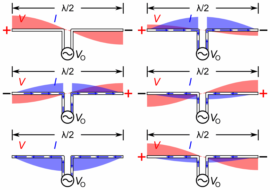
The picture from Wikipedia below clearly shows that the voltage is always zero at the center. My understanding is that this picture shows the standing waves on a dipole. The standing waves are the result of the applied AC voltage across the feed point and vary in amplitude over time but have a fixed voltage profile in space along the length of the dipole. I thought that anywhere along the length of the dipole ohms law always applies.

Dipole standing waves animation

Is the 'voltage' in the picture the voltage potential with respect to the center of the dipole ? and the one which results from that applied to the feed point ? The applied voltage potential difference results in a current which is the movement of electrons in the dipole in one direction during the positive half cycles of the ac waveform and in the opposite direction during the negative half right ?

What am i missing.

Is the voltage not really zero but rather I / Z = I / 75 + j 0 which is not zero ?

And then, if the voltage is not really zero, how come it's ok to connect the center of the driven element in a yagi to the boom because the voltage at the center is zero ?

Someone please help before my brain implodes !!!! :)

$\endgroup$
8
  • 1
    $\begingroup$ Welcome to AR! Maybe it's worth noticing that it's impossible to have both conductors at the same point (a feedline with 0 distance between conductors will have 0 impedance. So this small distance already accounts for some voltage to be present at the feed "point". $\endgroup$
    – Juancho
    Commented Oct 26, 2018 at 15:16
  • $\begingroup$ Is that animation correct? $\endgroup$ Commented Oct 26, 2018 at 19:45
  • 1
    $\begingroup$ I don't see how it could be for a 1/4 wave dipole. If these red and blue areas are trying to represent instantaneous voltage and current, they are 90 degrees out of phase, meaning the feedpoint impedance is purely reactive, meaning it's impossible to transfer any real power to it. This antenna could never radiate! $\endgroup$ Commented Nov 3, 2018 at 23:15
  • 1
    $\begingroup$ correction: I mean 1/2 wave dipole $\endgroup$ Commented Nov 3, 2018 at 23:31
  • 2
    $\begingroup$ The animation is wrong, on several points. As pointed out in several companion posts, "voltage = 0 at the center of a half wave dipole" is a convenient analytical construct, wherein the voltage at any point arbitrarily close to the center is +/- V/2. $\endgroup$
    – Brian K1LI
    Commented Nov 4, 2018 at 15:17

4 Answers 4

7
$\begingroup$

Look closer at the diagram. At the two wires coming from the source, the voltage is NOT always zero. The only way for the voltage at the center point to be zero is for the two source wires to occupy the same point which is impossible. Think about the voltage as an electric field which is indeed zero at the point halfway between the two wires.

$\endgroup$
2
  • $\begingroup$ I've been looking closely at this diagram among other things for about 2 years or so. What i discovered is that the voltage in the image is the actual voltage of the standing wave present on the antenna elements, it's not the electric field surrounding the elements. The standing wave is apparently circulating reactive energy present due to the antenna being a resonant system. $\endgroup$
    – Andrew
    Commented Aug 25, 2021 at 11:45
  • $\begingroup$ For a resonant dipole, the voltage on the inner ends of the elements is always zero during each cycle of applied RF at the source feed points and the current of the standing wave is in phase with the applied RF at the feed points, and this is the reason why a resonant antenna has no reactance in the feed point impedance. The image is incorrect in that it shows the voltage to be zero in the middle of the gap where there is no metal which is ridiculous. $\endgroup$
    – Andrew
    Commented Aug 25, 2021 at 11:47
4
$\begingroup$

The simple answer is that the graphic is not accurate. There is an RMS voltage present at the center feed point of the dipole that follows Ohm's law relative to the feed point impedance.

Most likely, the graphic is attempting to make the point that a center fed half wave dipole is fed at the current maxima. As such, the feed point voltage is therefore at its minima - but not zero.

$\endgroup$
9
  • $\begingroup$ Hi Glen, thanks. Does this mean then that the AC signal starts it's cycle at the feedpoint at a voltage of E = + (I / Z), where Z = 75 +j0, propagates to the end of the element, then is reflected back towards the feedpoint 180 deg out of phase and ends up back at the feedpoint at the end of that cycle and with a voltage of E = - (I / Z) ? $\endgroup$
    – Andrew
    Commented Oct 30, 2018 at 3:54
  • $\begingroup$ That article and animation on Wikipedia give the impression that there is one waveform across the entire length of the dipole which is moving through zero volts at the center, when there are actually two separate waveforms each on it's own 1/4 wave element of the dipole, 180 deg out of phase with each other and both only ever reaching a minumum voltage magnitude of E = I / Z. $\endgroup$
    – Andrew
    Commented Oct 30, 2018 at 3:56
  • 2
    $\begingroup$ @Andrew Keep in mind that the ~75 ohms impedance is a result of the standing wave that develops on each half of the dipole. If you could measure the "surge impedance" (the impdedance at the very instant a signal is applied) of the antenna, you would find a totally different value. This is essentially the same effect of the transformed input impedance of a transmission line due to reflections on the line. The surge impedance is the characteristic impedance (e.g. 50 ohms) of the line but the steady state impedance is quite different due to the reflection(s) from a mismatched load (and source). $\endgroup$
    – Glenn W9IQ
    Commented Oct 30, 2018 at 11:13
  • 1
    $\begingroup$ It's more accurate to say there's an RMS electric potential difference at the feedpoint. But there is also a point of zero electric potential in the middle of the dipole. Otherwise, how could we go from a positive electric potential at one end to a negative potential at the other end with a finite electric field intensity? $\endgroup$ Commented Nov 5, 2018 at 2:33
  • 2
    $\begingroup$ @Andrew I explain electric potential in my answer. $\endgroup$ Commented Nov 5, 2018 at 13:04
4
$\begingroup$

After all this time no one has actually provided a complete answer to this question so after some investigation i have answered it myself.

Thank you to those people who did give answers however.

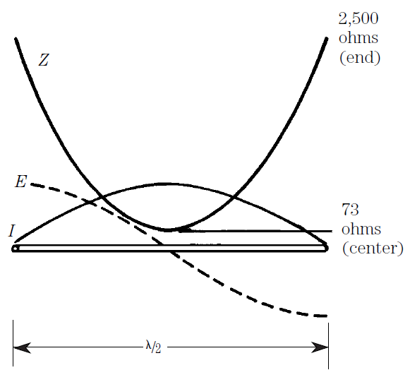
The animation in my question is related to the graph shown below. This graph which appears in numerous text books is confusing and misleading, as is the animation in my question.

enter image description here

The graph appears to show a snapshot in an instant of time of the voltage and current of the standing wave on a 1/2 wave dipole when the current is at a maximum, along with the resultant impedance Z.

The graphs confuses the reader in the following three ways.

  1. Any normal person who looks at this graph would assume that the impedance Z at each point on the antenna is the voltage of the standing wave divided by the current of the standing wave at each point according to ohm's law. Then the astute reader asks : how can Z at the center be 73 Ω when the voltage at the center is 0 ? ... Z = E/I so Z = 0/I = 73 Ω ?

  2. The impedance Z is shown as a single number so you get the impression that this impedance Z is a real number which doesn't have any reactance and so no relationship in phase with anything.

  3. The graph shows that the dipole is all one piece and not split in the middle.

To clarify, voltage here means the single ended AC RF voltage potential in volts present on the antenna elements at any point with respect to earth or zero volts, and current means AC RF current flowing through the antenna elements in amps. Voltage and current could be specified in peak, peak to peak, average or RMS, so long as the same units are used in the one context.

In truth the graph is showing the correct distribution of the voltage and current of the standing wave on a 1/2 wave dipole, however the impedance Z it depicts is actually the real part of the feed point impedance which would be present across two feed points terminals positioned along the various points along the length of the dipole elements.

The feed point impedance isn't the voltage of the standing wave divided by the current of the standing wave, but rather is a complex quantity equivalent to the differential voltage of the applied source across the two feed points divided by the resultant current of the standing wave at the feed points, the real part being equal to the radiation resistance of the antenna. For a series current fed center feed point the real part of the impedance is as everyone knows about 73 ohms and for a resonant dipole the current of the standing wave is in phase with the voltage of the applied source at the feed points.

The voltage of the standing wave divided by the current of the standing wave at any point along the antenna is actually called the Wave Impedance, and is a complex quantity which changes along the length of the antenna according to ohm's law. The wave impedance present at each point along the antenna isn't the same thing as the feed point impedance present across two feed point terminals.

The graph confuses feed point impedance with wave impedance and gives the reader the impression that the wave impedance is the feed point impedance by plotting standing wave voltage and current along the dipole with the real part of the feed point impedance. The impedance of free space you read about everywhere is actually the wave impedance of free space.

The animation in my question was taken from the Wikipedia article for a Half Wave Dipole. The text in the article does a very bad job at explaining what the animation is. The voltage and current in the animation are that of the standing wave on the antenna, which is circulating reactive stored energy present due to the fact that the antenna is a resonant system. The voltage and current of the standing wave are close to 90° out of phase with each other. The departure of phase difference away from 90 ° is the in-phase component of the standing wave which is responsible for radiation, the out of phase energy of the standing wave remains in the antenna. The animation erroneously shows that the voltage of the standing wave exists in the gap between the two feed points and so the voltage of the standing wave at the feed points is not always zero during each cycle of applied RF. This is not the case for a resonant antenna where the voltage of the standing wave which is about 90° out of phase with the applied RF at the feed points is always zero at the feed points.

I contacted the author of the animation in Wikipedia and managed to convince him to update the image, although the text in the article still doesn't explain the relationship between feed point impedance, and phase of the source and standing wave of a dipole antenna.

A plumbers delight yagi with the driven element connected to the boom at the center only works when the electrical length of the driven element is exactly 1/2 λ where the center of the driven element is in fact a zero volts all the time, and when its used with a gamma match or similar. In this configuration where the dipole is all one piece, the feed point impedance Z is seen between the center of the dipole and the end of the gamma match, as compared to between the two inner ends of the elements of a dipole split in the middle.

$\endgroup$
0
1
$\begingroup$

"Voltage" is not a very specific term: it only means "the value of something measured in volts". You might as well ask, "How can a sheet of paper have a meterage of 0.1 mm when it's on Mt. Everest with a meterage of 8848 meters?" Of course comparing thickness to elevation doesn't make much sense, even though both are measured in meters. But if you'd never been introduced to the concepts of thickness and elevation because they were both commonly called "meterage", it would be quite confusing.

So maybe it will help to understand exactly what thing is being measured by "voltage".

electric potential difference (volts)

When someone says "the voltage of this battery is 1.5 volts", they are measuring electric potential difference. This kind of voltage is always a difference between two points. An electric potential difference of 1.5 volts means for each coulomb of electric charge moved from the first point to the second point requires 1.5 joules of work. It is similar to saying "this hill is 10 meters tall", which says something about how much work must be done to lift a rock from the base of the hill to the top.

The feedpoint in an antenna isn't a point in the mathematical sense. So when discussing the voltage at the feedpoint, someone could mean the electric potential difference between the usually two parts of the feedpoint, like the center conductor and shield of a coaxial connector.

electric potential (volts)

When someone says "the voltage at the center of a dipole is zero" they are measuring electric potential. Protons and electrons (and other fundamental particles) have an electric charge. Opposite charges attract, and like charges repel through the electromagnetic force. To pull two opposite charges apart increases their electric potential, just like pulling a rock away from Earth increases its gravitational potential.

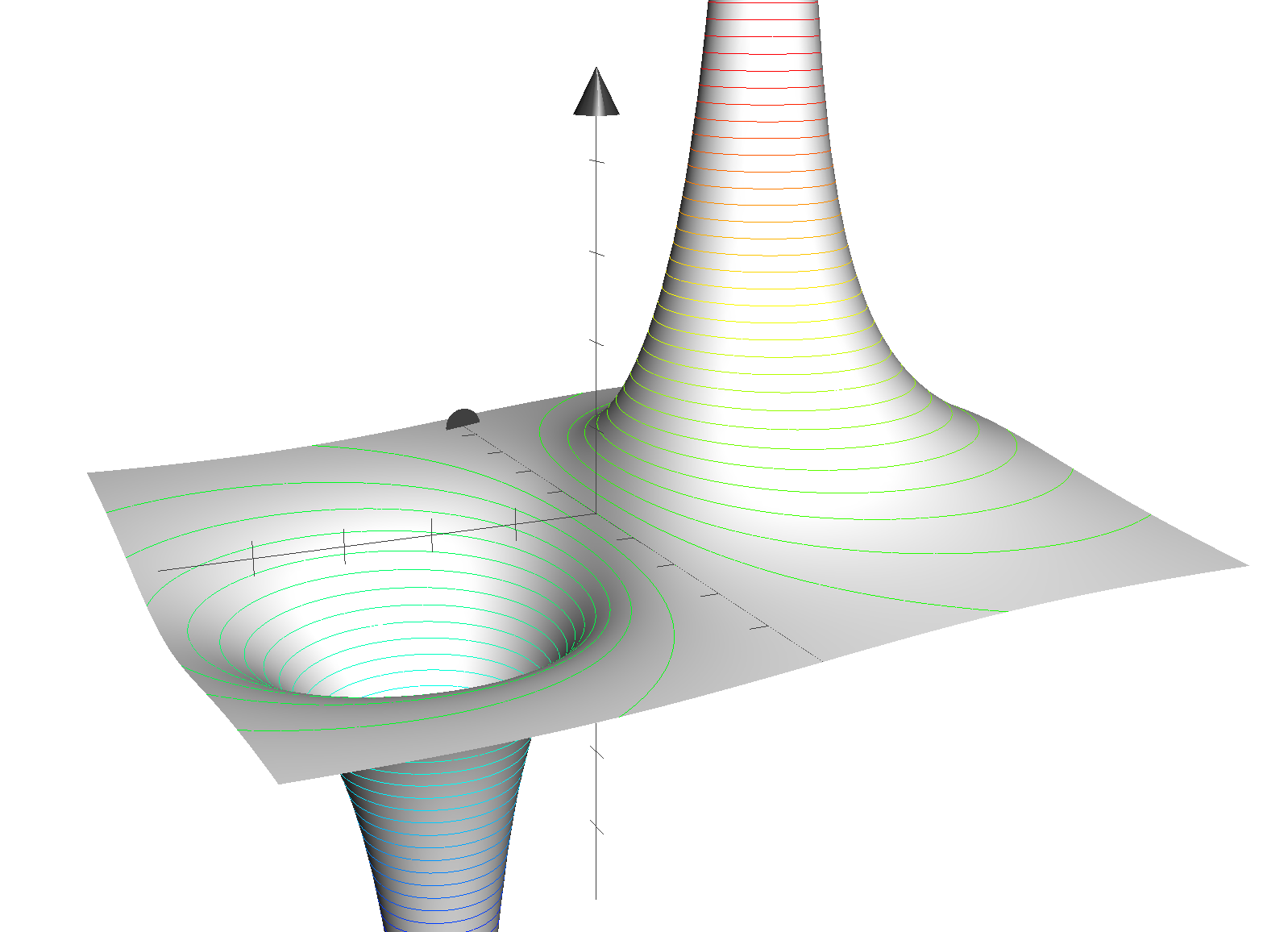
Unlike electric potential difference, electric potential can be defined on just one point. You've no doubt you've seen visualizations of gravity wells where massive objects pull down a rubber sheet. We can define a similar visualization for the electromagnetic force, and since we have both positive and negative charge there can be wells and hills:
enter image description here

The height of this sheet is the electric potential. At infinity the sheet is flat, this is by definition an electric potential of zero volts. The colored lines are contours with constant potential: moving around them neither increases nor decreases electric potential. Moving up or down one volt requires 1 joule of work per coulomb of charge moved.

Notice there's one contour that's hard to see: it's a straight line directly on the y axis, equidistant between the two charges. Because it's equidistant from two equal but opposite charges, the potential here is zero volts. This is what "voltage is zero at the center of a dipole" means.

electric field intensity (volts per meter)

What is not zero is the electric field intensity. It's the gradient of electric potential, and measured in volts per meter. This value is not zero at the center of a dipole: as you can see there's actually a quite steep slope at the origin of the graph.

And here I believe lies the crux of your issue. If you've done any lumped circuit analysis, you've probably equated "voltage" to "electric potential difference". That difference gives rise to an electromotive force, and if there's a conductive path across the distance, current. But when making the jump from lumped element analysis to electric field analysis, electric field intensity is the thing analogous to what you've been calling "voltage" in that it relates to electromotive force, and thus current.

some facts about dipoles without the word "voltage"

The center of a dipole is a single point. At this point, the electric field potential is zero, and the electric field intensity is non-zero. The non-zero electric field intensity means the mobile electrons in the antenna are moved by the electromotive force they experience, thus current is also nonzero at the center. The feedpoint is most likely two points, as in a coax center conductor and shield. Since these two points are separated by space, there is a nonzero electric potential difference between them.
$\endgroup$
4
  • $\begingroup$ Comments are not for extended discussion; this conversation has been moved to chat. $\endgroup$
    – Kevin Reid AG6YO
    Commented Oct 31, 2018 at 15:35
  • $\begingroup$ @Phil Thanks Phil i get it now, the main points being that electric potential is defined as energy / charge in joules per coulomb, and any one point has an electric potential. Electric potential difference is simply the difference in that electric potential between two points. And the center of a half wave dipole has an electric potential of zero volts, however the difference in potential between the two points of a feed point is the parameter which determines the feed point impedance Z = V (potential difference) / I (resultant current). $\endgroup$
    – Andrew
    Commented Dec 11, 2019 at 0:20
  • $\begingroup$ @PhilFrost-W8II "To pull two like charges apart" - should this be "unlike" charges? $\endgroup$
    – Brian K1LI
    Commented Jul 3, 2020 at 12:51
  • $\begingroup$ @BrianK1LI Yes, thanks for the correction. $\endgroup$ Commented Jul 3, 2020 at 23:25

You must log in to answer this question.

Not the answer you're looking for? Browse other questions tagged .