I would like to build a simple HF, VHF or UHF circulator to get a better understanding of how these devices work. Sadly at the moment I'm unaware of any articles or books that provide corresponding schematics and description. Could you please recommend a good source on the subject or maybe share a schematic?
-
2$\begingroup$ Are you looking for one that is made from coax and does not use ferrite? If so, you should edit your question and say so. Here's one using transmission lines, but I don't think that it is good enough for an answer. $\endgroup$– Mike WatersCommented Feb 8, 2020 at 18:50
-
2$\begingroup$ @MikeWaters took me longer than it should have to understand where that article was going, but it's really nice, kind of a circular bucket-brigade device made of "signal storage" delay lines. That's an elegant active way to build a circulator. I think it actually more than suffices for an answer if you can just explain that in one or two sentences! (1963, this must have been way harder than it is now: these days, I can simply buy an analog switch IC with three poles and no problems with switching at 10 MHz, instead of the slightly convoluted diode-based triphase 3.33 MHz oscillator they used) $\endgroup$– Marcus MüllerCommented Feb 8, 2020 at 19:19
2 Answers
Puh! That's a big one you're planning:
Most circulators are passive, magnetic material circulators:
These circulators are basically a three-port resonant cavity in a cylindric shape, where the cavity is filled with ferrimagnetic material, typically special ferrite disks.
The electromagnetic properties of magnetized ferrite are used to break up the geometric symmetry – now energy flows more in one direction (say, counterclockwise) than in the other (cw).
Thus, the magnetic properties of the circulator material become pretty crucial for it to work at all; it sounds like a bit of a daunting task to build one from scratch, but since you're not afraid to do so:
Pozar's Microwave Engineering has a short section on magnetic circulators (section 9.6 in the third edition); it's rather advanced.
corresponding schematics
Not being a component that is representable in electronics, but only in field/wave propagation terms, there's no electric schematic that you could find.
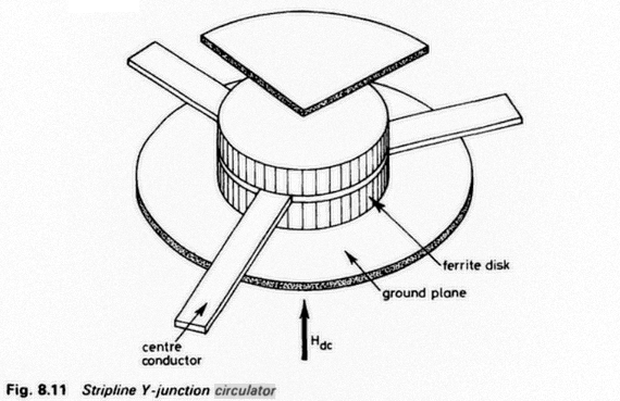
Here's a drawing of how a stripline Y-junction circulator might be built, from a book titled Ferrites at Microwave Frequencies.
You'll notice that circulators are inherently frequency-selective due to their cavity nature. So, you'll need the tools to build a well-defined cavity for your frequencies of interest, access to the raw ferrimagnetic discs, the ability to fix, shift them very finely, and potentially to rework them without them losing ferrimagnetism.
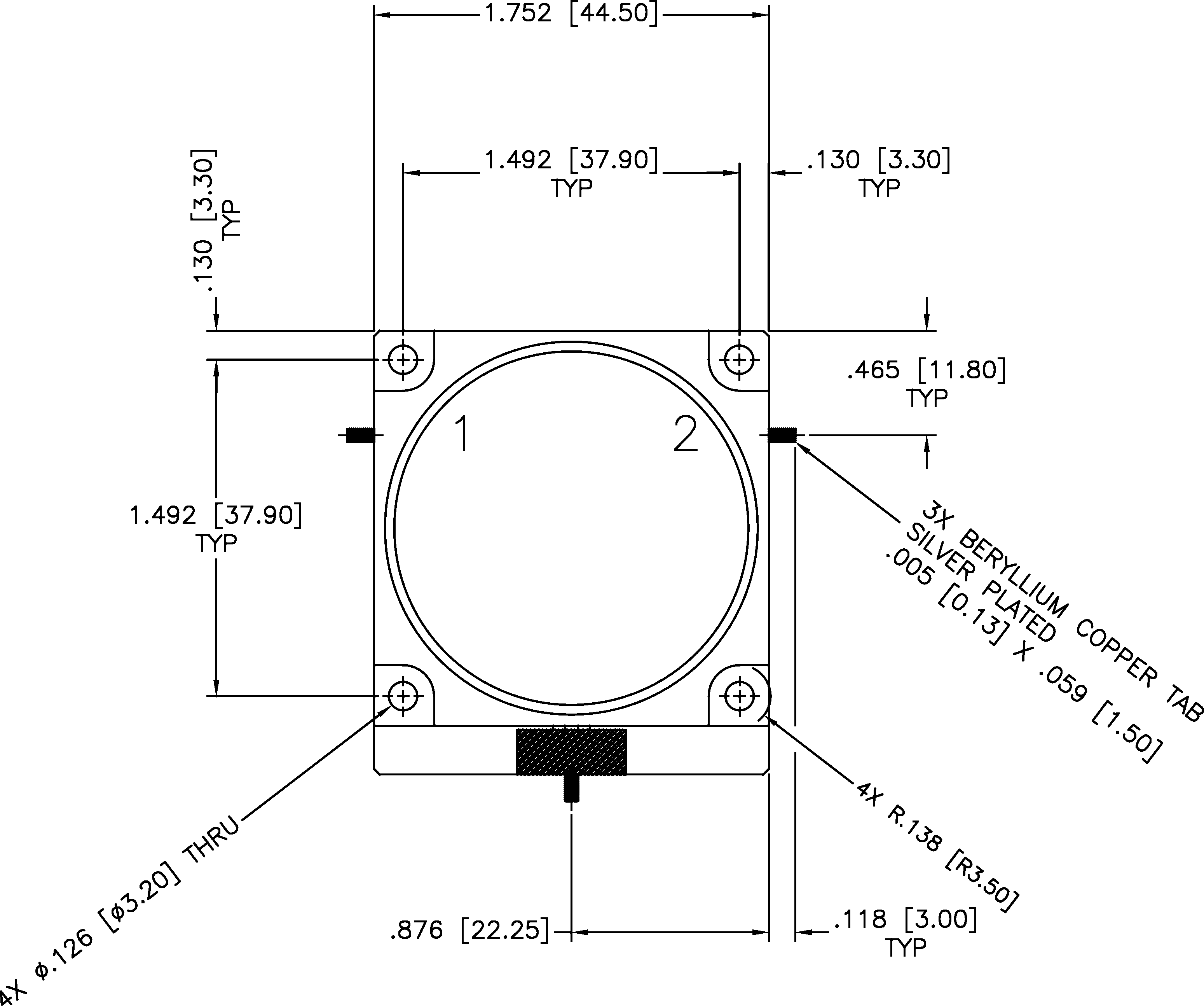
When you put all this into a case that holds the elements into place and ensures all the dimensions, you end up with something like source pdf:
-
1$\begingroup$ Thanks for the reply! If I'm not mistaken there are several ways to make a circulator, including one that uses coax cables. However I might be wrong. $\endgroup$ Commented Feb 8, 2020 at 13:02
-
2$\begingroup$ I wouldn't be aware of any non-magnetic, yet passive, solution to the problem: coax is inherently a symmetric thing, and I don't see how you could build a circulator with that. Note: a circulator is not the same as a directive coupler! $\endgroup$ Commented Feb 8, 2020 at 15:21
-
1$\begingroup$ @MikeWaters here's a stripline single-Y-junction ferrimagnetic disk circulator: drawing; roughly, 4cm × 5cm. $\endgroup$ Commented Feb 8, 2020 at 18:33
-
1$\begingroup$ Coax alone wouldn't work – you need an active component, like the rotating switch array in the article you linked. $\endgroup$ Commented Feb 10, 2020 at 8:59
-
1$\begingroup$ Please see my completely revised answer, Marcus. I meant coax with ferrite, magnets, etc. as every circulator apparent requires. $\endgroup$ Commented Feb 10, 2020 at 14:36
A circulator can probably be constructed from coaxial cable. However, you will also need ferrite and magnets.
From https://wa8dbw.ifip.com/Circulator.html :
A circulator is best thought of as a "Magic Box" containing three transmission lines spaced 120 degrees apart. These transmission lines are placed between two disks of ferrite material. On the other side of the ferrite is a non-ferrous ground plane and then a magnet followed by a ferrous pole piece that shields the unit from external magnetic fields.
Usually on circulators designed for the VHF/UHF (50 - 512 MHz) frequencies will have a means of tuning each transmission line so that insertion loss and isolation can be optimized at the desired center frequency range.
From http://www.e-meca.com/rf-microwave-blog/isolator-circulator-basics:
An RF circulator is a three-port ferromagnetic passive device used to control the direction of signal flow in a circuit and is a very effective, low-cost alternative to expensive cavity duplexers in base station and in-building mesh networks. Examples of both applications will be covered later in this article.
To understand how these components control the signal flow, think of a cup of water into which you place a spoon and stir in a clockwise motion. If you sprinkle some pepper into the cup and continue to stir, you will notice that the pepper easily follows the circular motion of the water. You can also see that it would be impossible for the pepper to move in a counterclockwise direction because the water motion is just too strong. The interaction of the magnetic field to the ferrite material inside isolators and circulators creates magnetic fields similar to the water flow in the cup. The rotary field is very strong and will cause any RF/microwave signals in the frequency band of interest at one port to follow the magnetic flow to the adjacent port and not in the opposite direction.
Description of circulator, from Wikipedia article:
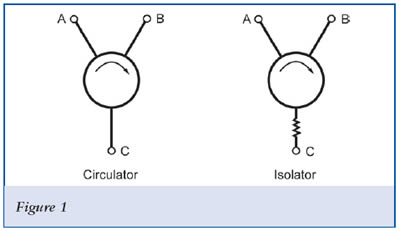
A circulator is a passive, non-reciprocal three- or four-port device, in which a microwave or radio-frequency signal entering any port is transmitted to the next port in rotation (only).
Here's a circulator using transmission lines. Per Marcus Müller:
... It's really nice, kind of a circular bucket-brigade device made of "signal storage" delay lines. That's an elegant active way to build a circulator.
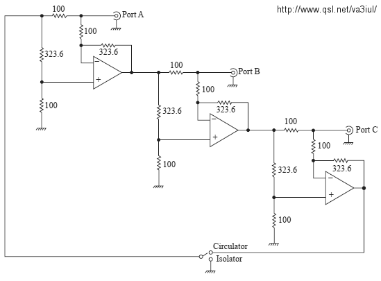
This circulator schematic from VA3IUL uses CLC406 op-amps and covers DC to 100 MHz.
Found at the YO3DAC VA3IUL Homebrew RF Circuit Design Ideas website.
Here's a circulator using no magnets based on parametrically-modulated coupled-resonator loops behind a $9 paywall.
I found that by Googling homemade rf circulator -vector. There are information and construction articles and even a video there. (I did not follow many of those links in the Google search results.)
-
$\begingroup$ I removed the info and image about the 4 port hybrid ring, because it is not a circulator. $\endgroup$ Commented Feb 10, 2020 at 3:27
-
$\begingroup$ Yea but you cant transmit 1,000 watts through any of those! A circulator is only a useful element during transmit even barefoot @ 100 watts thats a tall order! $\endgroup$ Commented Jan 1, 2021 at 16:22


