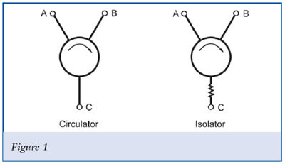
A circulator can probably be constructed from coaxial cable. However, you will also need ferrite and magnets.
From https://wa8dbw.ifip.com/Circulator.html :
A circulator is best thought of as a "Magic Box" containing three transmission lines spaced 120 degrees apart. These transmission lines are placed between two disks of ferrite material. On the other side of the ferrite is a non-ferrous ground plane and then a magnet followed by a ferrous pole piece that shields the unit from external magnetic fields.
Usually on circulators designed for the VHF/UHF (50 - 512 MHz) frequencies will have a means of tuning each transmission line so that insertion loss and isolation can be optimized at the desired center frequency range.
From http://www.e-meca.com/rf-microwave-blog/isolator-circulator-basics:
An RF circulator is a three-port ferromagnetic passive device used to control the direction of signal flow in a circuit and is a very effective, low-cost alternative to expensive cavity duplexers in base station and in-building mesh networks. Examples of both applications will be covered later in this article.
To understand how these components control the signal flow, think of a cup of water into which you place a spoon and stir in a clockwise motion. If you sprinkle some pepper into the cup and continue to stir, you will notice that the pepper easily follows the circular motion of the water. You can also see that it would be impossible for the pepper to move in a counterclockwise direction because the water motion is just too strong. The interaction of the magnetic field to the ferrite material inside isolators and circulators creates magnetic fields similar to the water flow in the cup. The rotary field is very strong and will cause any RF/microwave signals in the frequency band of interest at one port to follow the magnetic flow to the adjacent port and not in the opposite direction.
Description of circulator, from Wikipedia article:
A circulator is a passive, non-reciprocal three- or four-port device, in which a microwave or radio-frequency signal entering any port is transmitted to the next port in rotation (only).
[Here's a **circulator using transmission lines**](https://ieeexplore.ieee.org/document/1444937). Per Marcus Müller:
... It's really nice, kind of a circular bucket-brigade device made of "signal storage" delay lines. That's an elegant active way to build a circulator.
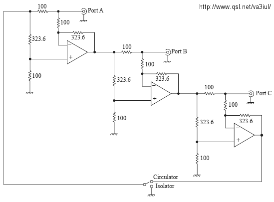
This circulator schematic from VA3IUL uses CLC406 op-amps and covers DC to 100 MHz.
Found at the YO3DAC VA3IUL Homebrew RF Circuit Design Ideas website.
[Here's a circulator using **no magnets** based on parametrically-modulated coupled-resonator loops](https://www.nature.com/articles/nphys3134) behind a $9 paywall.
I found that by Googling homemade rf circulator -vector. There are information and construction articles and even a video there. (I did not follow many of those links in the Google search results.)

