Whatever modulation we use, there's a baseband signal we wish to transmit (music, voice recording, whatever), which somehow modulates a carrier to produce the output signal.
Your question suggests you are primarily concerned about how the frequency domain representation of the baseband translates to the frequency domain of the output. This is a valid thing to wonder, and it has particular relevance to determining how much bandwidth will be occupied by the transmission for a given input, for example. But it's not always the best way to understand a modulation scheme. That's better done in the time domain.
For AM, we modulate the amplitude of that signal. Let's say the baseband signal is a square wave. Here's an example of a "loud" square wave and AM, with the baseband in red, and the output in blue.

With a quieter baseband input, the variation in amplitude of the output is less.

For FM, we modify the frequency instead of the amplitude. Here again is a loud square wave. Note the large variation in frequency between the periods where the square wave is a large value, versus where it's a low value:

With a quieter baseband input, the variation in frequency is less:

Of course in practice the baseband signal will be something more interesting than a square wave. Here's an AM example with a more complex input:

Note the baseband waveform can be anything at all: it can have any number of frequency components, at any number of amplitudes. But that's not necessarily relevant: all we need to know at any instant is the value of the baseband signal, and that's what the amplitude of the carrier is.
And now with FM:

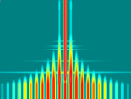
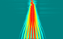
What does FM look like in the frequency domain? Let's generate some waterfall plots with a sine wave baseband which changes only in frequency or amplitude.
Altering the baseband amplitude increases the amplitude of the FM sidebands. Here's a sine wave baseband, increasing in amplitude.

Increasing the baseband amplitude is equivalent to increasing the modulation index or deviation. You can see that even with just a sine wave baseband, there are several sidebands generated. Mathematically, these repeat out to infinity, but in practice they can be ignored at some point. A typical modulation index will be such that there are at least a few sidebands, otherwise most of the power would be in the carrier, making inefficient use of transmitter power.
Altering the baseband frequency changes the spacing between the sidebands. Here's a sine wave input of constant amplitude, increasing in frequency:

Of course in practice baseband will contain many frequency components, varying in amplitude. Because even a single baseband frequency generates several sidebands, the individual frequencies in baseband create overlapping output frequencies and the result is a jumbled mess, visually.


