5
$\begingroup$

I tried to build a multiband EFHW antenna as described in articles by PA3HHO, PD7MMA, G0KYA and many others. I decided to start with a short 40/20/(15?)/10 meters version without any loading coils. Surprisingly, no matter what I tried I didn't manage to make the antenna work on more than one band. I was hoping someone could explain where my mistake was.

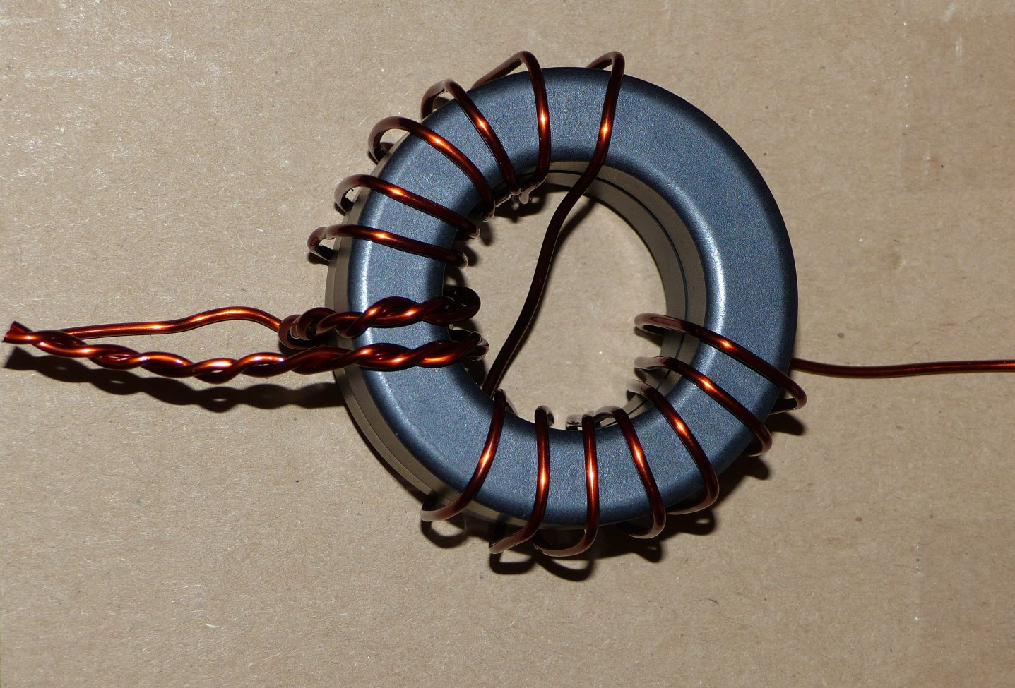
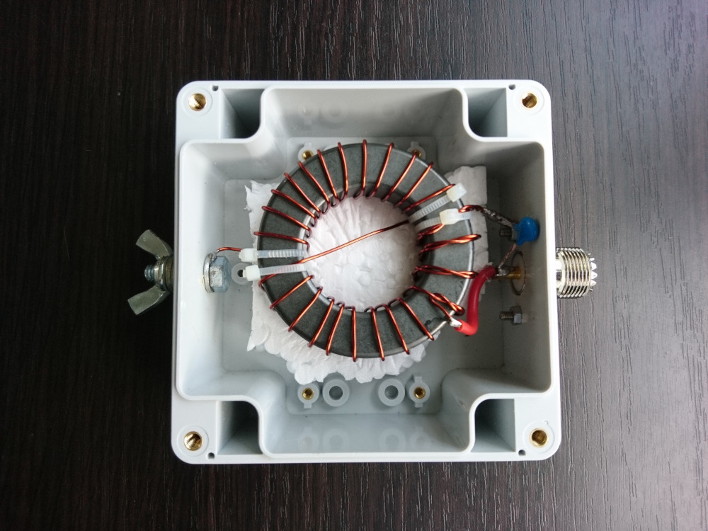
I used FT240-31 ferrite core for 64:1 (and later - 49:1) transformer, about 18 meters of wire (П274М, Russian equivalent of British D10 - I've used it many times before for long wires, dipoles and delta loops) and 2 meters of RG58 as a feed line and counterpoise at the same time. The second end of the cable was connected to a 1:1 balun. The antenna was installed in inverted-L configuration on a 10 meters long fishing rod.

Here is a photo of a transformer and 100 pF capacitor:

enter image description here

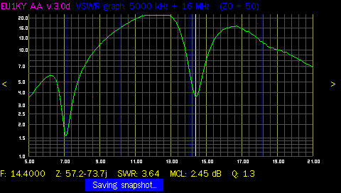
I easily got SWR from 1.5:1 to 1:1 on 40m. However the best I could get on 20m is 4:1:

enter image description here

I tried to get rid of the capacitor, to change it value with a variable capacitor, to change the 64:1 transformer to the 49:1 one, to change the length of the antenna, etc. Currently I spend three weekends on this project. No matter what I tried I get a single band antenna.

It looks like I'm missing something. Maybe the loading coil is not optional in this antenna, maybe it's important to use mix 43 (not 31) as other authors did, maybe something else. What would you do to make the antenna work on 2+ bands?
$\endgroup$
10
  • 1
    $\begingroup$ Too many web sites to review. Please tell us which antenna you are trying to duplicate. $\endgroup$
    – Brian K1LI
    Commented Jul 29, 2019 at 17:04
  • 1
    $\begingroup$ Have you tried using a counterpoise wire that isn't also a feed line? $\endgroup$
    – rclocher3
    Commented Jul 29, 2019 at 17:45
  • 1
    $\begingroup$ @BrianK1LI I believe EFHW (end fed half wave) is a most commonly used name. It is a half wave antenna (basically a dipole) that is fed almost from the end. Almost - because it requires a counterpoise ~0.05 lambda to get a non-reactive impedance. A 64:1 or 49:1 transformer is used to match the impedance (2500..3200 Ohm) of the feed line. Part of the feed line is commonly used as a counterpoise. In this case the feed line is separated from the rest of the coax with a 1:1 balun. The legend tells that antenna supposed work on multiple bands (1 lambda, 1.5 lambda, etc). $\endgroup$ Commented Jul 29, 2019 at 19:53
  • 2
    $\begingroup$ The counterpoise could be your problem. I think you should try a counterpoise wire under the antenna wire as an experiment. $\endgroup$
    – rclocher3
    Commented Jul 29, 2019 at 20:00
  • 1
    $\begingroup$ I agree that the feedline is probably acting as part of the antenna. This is why I asked for a reference to the antenna you are trying to duplicate. Your description is too general for us to provide concrete advice. $\endgroup$
    – Brian K1LI
    Commented Jul 30, 2019 at 0:04

6 Answers 6

5
$\begingroup$

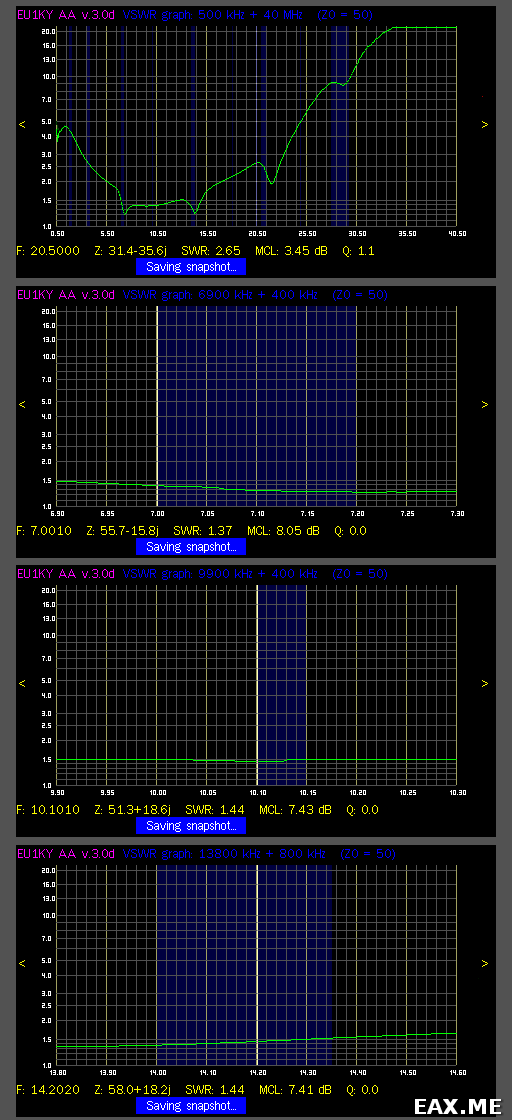
Eventually I managed to make the antenna work on more than one band. I used a modeller (CocoaNEC) to approximately determine the impedance on each band of interest for my antenna configuration (inverted-V on a 10m long fishing rod). The impedance was about 2450 Ohm. Thus I rewinded the transformer to 1:49. Also I used a 1:1 balun (8 turns of RG58 on FT240-31 core) to eliminate any common mode current. Using a variable capacitor I've found a capacitance (138 pF in my case) that gives the best SWR plot:

enter image description here

No counterpoise was needed since it's role was played by the coax in the 1:1 balun. Then I replaced a variable capacitor with a constant NP0 capacitors. You can find a little more details here. The article is in Russian, but Google Translate should manage.

The antenna was tested on all band where it has SWR < 3: from 80m to 15m. QSOs were made on all these band. However, subjectively the overall performance of the antenna is not great comparing to the performance of a regular dipole. I wouldn't recommend trying to repeat it, at least definitelyly not with cores I've used.

$\endgroup$
4
  • 1
    $\begingroup$ Congratulations on solving your problem, Aleksander. Did you ever attempt to measure the loss of the matching network? $\endgroup$
    – Brian K1LI
    Commented Sep 29, 2019 at 17:03
  • $\begingroup$ @BrianK1LI I was just going to mention that! Whenever I have seen VSWR plots like that, it was always due to high losses somewhere. Aleksander, I suggest that you transmit a carrier (perhaps 100 watts) and see how warm your matching network is after 30 seconds. $\endgroup$ Commented Sep 29, 2019 at 22:52
  • 1
    $\begingroup$ The matching network doesn't get hot if you transmit 100W CW for 30 seconds. However I noticed that after calling CQ in FT8 for half an hour using 30W the core gets quite warm. You can still safely touch it however - I would say it's no more than 50 C. No doubt there are losses in the matching network. However I 'm having difficulties to estimate how large (in %) these losses are. $\endgroup$ Commented Sep 30, 2019 at 6:58
  • $\begingroup$ Estimating how large the losses are by simply measuring the temperature rise over time is difficult at best, unless you use a calorimiter. A significant % of the heat is undoubtedly radiating, unless you have good insulation preventing that from happening. ;-) However, if "quite warm" means that you cannot push your finger on the core and comfortably hold it there for at least 5 seconds, then you have significant losses. Having said that, part of your losses may be in the earth. $\endgroup$ Commented Sep 30, 2019 at 19:24
1
$\begingroup$

See this YouTube video titled: "The 49:1 Half-Wave End-Fed Antenna Transformer, Part 1." https://www.youtube.com/watch?v=MgZap6xWZLs

It says:

49:1 with 3 to 21 windings on the transformer is good for 40m & 80m bands

and

49:1 with 2 to 14 windings on the transformer is good for 40m, 20m & 15m bands.

I made the 2 to 14 with an FT240-43 toroid and 100 pF capacitor. I connected a 66ft vertical wire up a tree with 15 meters of coax and SWR is less than 1.3 on 40m, 20m & 15m bands.

$\endgroup$
1
  • 1
    $\begingroup$ Hello and welcome to ham.stackexchange.com! $\endgroup$
    – rclocher3
    Commented Aug 24, 2020 at 15:22
0
$\begingroup$

I used a 2 to 14 wrap on a T240-31. Close wrap first 7 turns and run cross turn close to the first 7 then close wrap the last turns. You can adjust the spacing and it will lower or raise your SWR. Works for me, only had to adjust it once. Then I hot glued the turns so they wouldn't move. Also check out Steve Ellington videos on his research. This was his idea. Anything is worth a try.

$\endgroup$
2
  • $\begingroup$ Hi, and welcome to ham.stackexchange.com. Your post is relevant and interesting, but it doesn't answer the question. This site is different from typical forum-style sites; we're trying to get high-quality answers to questions. The tour explains the idea. It might seem weird at first, but the format has its advantages: expertise is recognized and there are no trolls. I hope you check it out and stick around. $\endgroup$
    – rclocher3
    Commented Aug 11, 2019 at 4:44
  • $\begingroup$ Hello Rick, can we assume that what you describe allows your EFHW to work on more than one band? If so, this does answer the question; but can you please share more details? Also, I took the liberty to edit your answer to include a link to the 75 minute video that you may have meant. Is that the right one? $\endgroup$ Commented Sep 30, 2019 at 19:06
0
$\begingroup$

Please excuse me for perhaps stating the obvious, but you need to cut the antenna wire for a half wave on 40M approx 66 feet, it will work ok on 20 and 10 Metres where there are multiple half waves on a 66 foot wire.

My homebrew EFHW 49:1 matching unit is attached to 132 feet of wire and works very nicely on the normal harmonically related bands 3.5 - 28 MHz and not too badly on the WARC 10.1, 18 and 24 MHz bands. Photo before I added the capacitor.

enter image description here

I used dual FT240-43 cores and 1.6mm enamelled copper wire 14 AWG.

Having been a seagoing radio officer, I learned to over engineer things a bit HI

73 and good luck Tony G3ZRJ

$\endgroup$
1
  • $\begingroup$ Hi Tony, Aleksander did cut his wire to be a half wavelength, and there is a clear minimum in his SWR curve at both 40m and 20m, so he must have cut the wire accurately. His problem is that the SWR is < 2:1 only on 40m, although he comes close on 20m. Any ideas? $\endgroup$
    – rclocher3
    Commented Nov 4, 2020 at 2:20
0
$\begingroup$

I think your original wire was too long, 29.5 feet (overall) and type 43 core/s should have been used for 40, 20, & 10 meters without a tuner and all bands 40 to 10 meters with a tuner and the transformer ratio should be 64:1 for this length. Ron W4BIN

$\endgroup$
2
  • $\begingroup$ Thanks, Ron. Although 29.5 feet is less than 9 meters. There is no way it can work on 40 meters, at least not as intended. $\endgroup$ Commented Dec 6, 2021 at 16:44
  • 1
    $\begingroup$ Hello Ron, and welcome to ham.stackexchange.com! Please consider expanding your answer to give more information, such as sources, and reasons why a particular wire length, core material, or transformer ratio would be better. $\endgroup$
    – rclocher3
    Commented Dec 6, 2021 at 23:12
-1
$\begingroup$

This is NOT 64:1 more like 144:1 and core is wrong must be 240-43 go back to the PA3HHO, PD7MMA, webb and read again the short an t with out smal coil wil be 10-20m only fit small coil it will be 19/20/and 40m Pieter

$\endgroup$
1
  • $\begingroup$ Hello Pieter, and welcome to ham.stackexchange.com! $\endgroup$
    – rclocher3
    Commented Jan 6, 2021 at 1:40

You must log in to answer this question.

Not the answer you're looking for? Browse other questions tagged .