6
$\begingroup$

There are multiple ways to couple antennas. It is said that an antenna is capacitive loose coupled if a small capacitor is used between the antenna and the parallel resonant circuit (like C2 in the image below). Such a loose coupling will increase the selectivity of the following parallel resonant circuit. That means the bandwidth of the parallel resonant circuit will be smaller. Therefore frequency parts of the signal which are farther away from the resonant frequency of the parallel resonant circuit will be "filtered out".

I understand, that a smaller capacitor means a looser coupling. The smaller the capacitor, the less energy will be transferred to the resonant circuit (therefore it is "loose" rather than "tight" coupled), due to an increasing capacitive reactance.

My question is: How can the increase of selectivity physically explained? It seems as if the capacitor suddenly acts like a bandpass. But why is that?

I googled a lot, but unfortunately everything I found just says "it is like that" or "do it like that" but not why this phenomenon is observed.
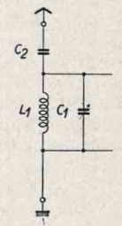
Antenna coupled to parallel resonant circuit with a small capacitor

$\endgroup$
1
  • 5
    $\begingroup$ Welcome to ham.stackexchange.com! $\endgroup$
    – rclocher3
    Commented Apr 2, 2020 at 17:34

2 Answers 2

2
$\begingroup$

I think if we were able to use perfect components, it would not matter. However, your antenna is not a perfect component. Is has many losses which result in a resistor R in its replacement diagram, in serial to C2. Now you can consider your antenna system as one resonant circuit consisting of: L/C of the wire, C2, L1, C1 and R.

Looking at the circuit this way helps me to understand why a looser coupling of the lossy C2/R component helps to increase the all over Q of the circuit. Because the smaller C2 gets, the more the high Q of C1, L1 comes into position.

We should keep in mind that having a small C2 will help to get a higher Q, which is desirable for active antennas (receiving antennas). On the other hand loose coupling will reduce the efficiency, if C2 does not match the L/C of the antenna.

$\endgroup$
0
$\begingroup$

Really short answer, since I'm just passing by:

What you state (narrow bandwidth for small capacitor) is not generally true, but

  • low bandwidth means "there's a narrow peak of strong resonance*
  • that's equivalent to "this is a very high-quality resonator"
  • In a series RLC resonator with a fixed resistive component (whether that is really a resistor), the damping factor goes with the square root of the capacitance; the less dampened a circuit is, the higher the quality of oscillation, the lower thus the bandwidth.
$\endgroup$
2
  • $\begingroup$ Thank you! Points 1 and 2 are what I tried to say, but your wording is better than mine. Regarding point 3: a. So the property of the (small*) capacitor to act as resistor is responsible for the damping? b. Can you give me a formula for the relationship between capacitance and damping factor? c. You are talking about a series RLC resonator, the resonator in the image is a parallel LC resonator with a capacity in series. Does the same apply of what you said? $\endgroup$
    – dudekowsky
    Commented Apr 2, 2020 at 20:21
  • 1
    $\begingroup$ I think the antenna contains the resistor. The more tightly coupled the L1/C1 tank is to the antenna, the more its Q is degraded from its unloaded Q. Keeping the capacitor small avoids loading the resonant circuit too much. $\endgroup$
    – tomnexus
    Commented Apr 2, 2020 at 20:39

You must log in to answer this question.

Not the answer you're looking for? Browse other questions tagged .