I'm learning to build radio receivers and transmitters. I've successfully build some oscillators, amplifiers and filters before and decided that to build a simple crystal radio would be a logical step further. I wanted to build a crystal radio for ~7-8 MHz because I have a good antenna for 40 m band and during the night there are always many strong AM signals (typically S9+30 and even above) around 7.200-7.300 MHz.
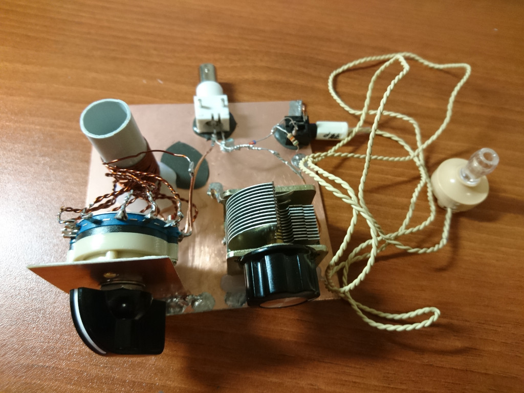
Here is how my radio looks like:
The inductance of the coil is about 8 uH. It has 12 taps with 6th tap around 3.7 uH. The capacitor is 12..365 pF, the diode - 1N34 and the resistor - 51 kOhm. One way or another (considering stray capacitance, not exact inductance of the coil, etc) it supposed to tune somewhere around the frequency of interest:
>>> from math import pi, sqrt
>>> L = 3/1000/1000 # 3 uH
>>> C = 130 / 1000/1000/1000/1000 # 130 pF
>>> 1/(2*pi*sqrt(L*C))
8059123.816756153
>>> C = 170 / 1000/1000/1000/1000 # 170 pF
>>> 1/(2*pi*sqrt(L*C))
7047499.335473463
I tested the radio using a signal generator and an oscilloscope and confirmed that the BPF (LC-network) works as expected. The radio is also capable to receive a 5 W CW signal from my transmitter with the transmitting antenna placed about 20 meters away from the receiving antenna. The radio doesn't receive anything when I transmit on 20 m band.
However no matter how I tried I didn't manage to receive any AM stations. I've noticed though that if I briefly transmit an 5 W AM carrier on the frequency of the AM station (not something I supposed to do...) I can hear this particular station reasonably well while I'm transmitting.
I tried to change the coil, the resistor and add/remove capacitors in series and parallel to the variable capacitor for quite some time. At this point I doubt that I will get any better results.
What brings me to the question I have. I don't know whether such a low sensitivity of a crystal radio is expected for this band (maybe this is the reason why most people make crystal radios for 0.5-1.6 MHz?) or maybe I did something wrong. Is it worth trying to make any further tests or improvements to the radio (in this case, which one?) or it's as good as a simple crystal radio will be and I should move forward to other types of receivers (e.g. superheterodyne)?
