3
$\begingroup$

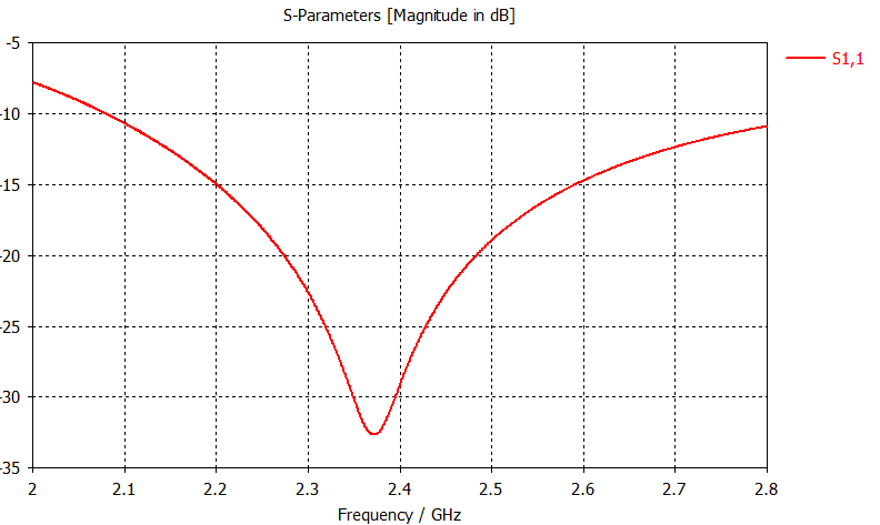
I am trying to design a loop antenna for operation at 2.4 GHz, I would like for it to have above 2.5 dB gain at 2.4 GHz and have relatively good return loss (<-10 dB).

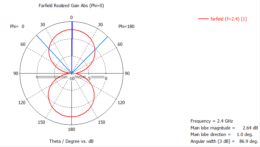
I have started my design as shown in the pictures. I am concerned with the radiation pattern cut at phi=90 degrees:

E-Cut

I feel as though this plane cut should be circular in shape. Is there any way I can adjust the antenna to produce the desired radiation pattern?

Front of antenna

Back of Antenna

S1,1

H-Cut

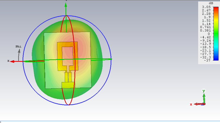
Farfield Pattern

$\endgroup$
7
  • 2
    $\begingroup$ If you want it to be circular in shape, then yes - make it circular in shape. If you mean "In this software I am using, how do I make it circular in shape?" then you need to say that - it would be especially helpful if you specified what that software is, in order to allow people to even consider answering the question. As it is, this question is either unanswerable, or answered with "if you want to make it circular, try making it circular" $\endgroup$
    – Scott Earle
    Commented Apr 19, 2018 at 4:01
  • $\begingroup$ Maybe you misunderstood my question? I want my antenna to produce a Fairfield cut that is circular in nature. The fact that I am using software doesn’t matter, as the software is a simulation software made to emulate reality. So if I were physically designing the antenna it would have the same result. My question is, what about the dimensions of the antenna can I tweak to end up with a circular Fairfield cut. $\endgroup$
    – amantonas
    Commented Apr 19, 2018 at 14:43
  • 2
    $\begingroup$ "I want my antenna to produce a Fairfield cut that is circular in nature". I think the OP meant Far-field rather than Fairfield. And that he wants the radiation pattern to be "circular" rather than the antenna itself. $\endgroup$
    – mike65535
    Commented Apr 19, 2018 at 15:25
  • 1
    $\begingroup$ Seem clear enough to me, with a little rewording. "Cut" is a planar cross-section of the far-field radiation pattern. He would like the radiation pattern in that plane to be omnidirectional. $\endgroup$ Commented Apr 19, 2018 at 21:41
  • 1
    $\begingroup$ But I’m an early riser! Ha! By all means reopen it, the edits do make it clearer $\endgroup$
    – Scott Earle
    Commented Apr 19, 2018 at 22:13

1 Answer 1

3
$\begingroup$

By nature, the radiation pattern of a small loop antenna will not be uniform in the azimuth. It will typically have the classic bipolar lobe pattern with nulls in the quadrature positions as shown in your plots.

You should either consider classes of antennas that are omnidirectional in the azimuth (e.g. monopoles, vertical dipoles, horizontal slot, etc.) or phase two loops that are oriented 90 degrees from one another. In the latter case, the pattern will be pseudo omni in the azimuth and the solution will likely require two PCBs and an interconnecting transmission line.

You state that you require 2.5 dB gain. Note that this is an ambiguous statement since there is no normative reference. It should likely be stated as either dBi or dBd gain. In professional circles, dBi is used almost exclusively but it still should be explicitly stated.

Note that you also specified an RL without stating the ZO of the transmission line, the output impedance of the transmitter, or the input impedance of the receiver. All of which are essential facts in order to engineer a solution that fully meets the requirement.

$\endgroup$
1
  • $\begingroup$ "monopoles, vertical dipoles ..." That's almost exactly what I was thinking, Glenn. A loop is just not going to do what the OP wants. $\endgroup$ Commented Apr 22, 2018 at 0:59

You must log in to answer this question.

Not the answer you're looking for? Browse other questions tagged .