25
$\begingroup$

I would like to add a balun/choke to my dipole for the reasons outlined in Using a balun with a resonant dipole. In the spirit of continued kit and/or DIY building for my ham shack, I set out to investigate how I might best proceed "from scratch".

Simply wind two conductors together over some sort of core?

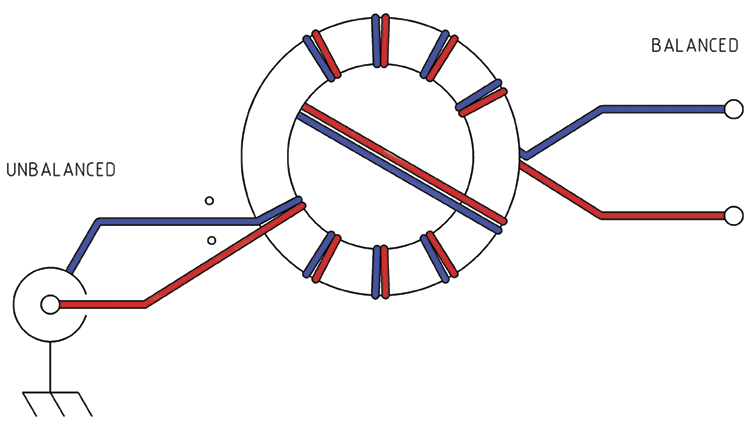
At http://vk6ysf.com/balun_guanella_current_1-1.htm a design is given for a 1:1 current balun that simply wraps a pair of wires around a toroidal core:

Simple bifilar winding around toroid, unbalanced in and balanced out

…or as http://vk5ajl.com/projects/baluns.php#current even shows:

A pair of wires wrapped around a nail

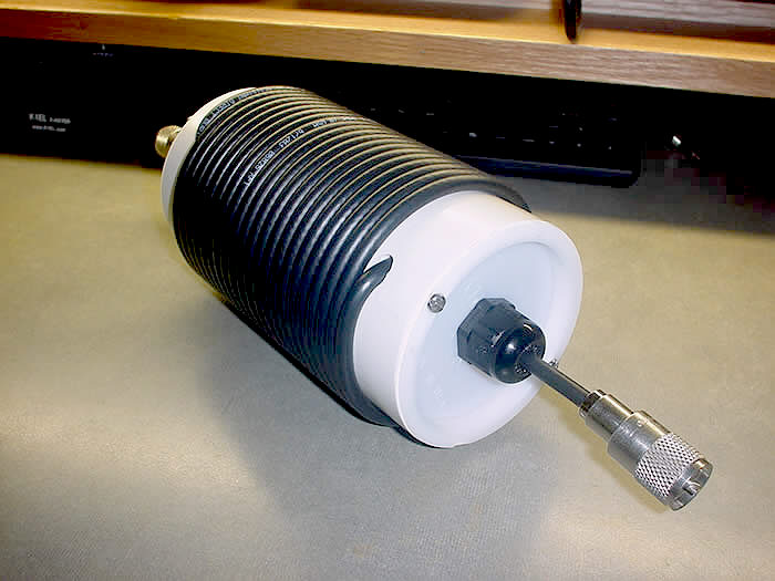
I suppose the air-wound "ugly balun" as demonstrated at http://www.hamuniverse.com/balun.html also fits in this same category, unless using coax in place of the bifilar winding somehow changes things?

Coax wrapped repeatedly around a large-diameter PVC tube

So that's all well and good, I guess.

Two tangled toroids?

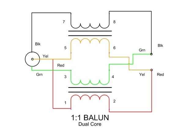
But then — under the same "Guanella balun" name as the first diagram above, no less! — I find that http://www.kn9b.us/guanella-balun presents this diagram:

Schematic of a 1:1 current balun using two bifilar windings on two separate toroids

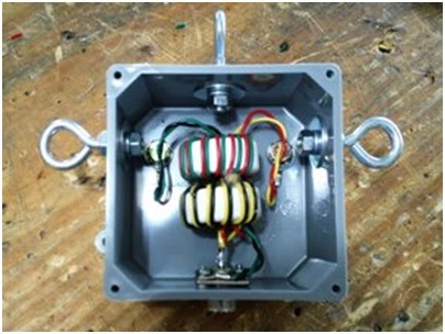
…which is to be built using two toroids resulting in something that looks like this:

Current balun using two toroids, assembled in a project box

Is there any benefit to this dual core balun over the single core type? What is the purpose of this sort of "push-pull" reminiscent design? Is it worth buying two toroids and going to twice the trouble of winding and sorting out which loose ends connect to which others, versus just winding a pair of wires around a rusty bolt, or wrapping some coax around some scrap PVC?
$\endgroup$

3 Answers 3

17
$\begingroup$

Baluns are a source of much confusion in the hobby, and are probably one of the most common causes of RFI, common mode noise reception, and poor antenna performance. Folks try to shoe-horn a lot of very complex values and characteristics in to a very linear way of thinking, and most of it is just flat wrong.

  1. Starting from the top: That design should in theory work fine, except the website is using a toroid for which I can find almost no tech data, and what little is available in the data sheet suggests it's meant for SMPS transformers and the like. This means it is quite likely to saturate, or potentially just not offer much of any choking impedance at higher frequencies. You might be able to justify using it for 160m, maybe even 80m, but above that, it's almost certainly at best ineffective, and at worst, very inefficient. Even on the lower frequencies, given the type of transformer they're typically used for, I suspect that choking impedance would be quite low.

    The counter winding technique is also at best needlessly complicated, and at worst can act to increase parasitic capacitance within the transformer, causing a reduction in performance, not the commonly claimed improvement. W8JI, K9YC, and VK1OD all failed to find any evidence of the supposed elimination of saturation with that winding style, in reality it likely just causes a complex eddy current which may lead to localized saturation in some areas of the toroid but not others.

    This design with a Type 43 or Type 31 (Amidon, Palomar, or Fair-Rite) T106 core would be fine for 40m and up on QRP, T200 or larger for 100w, especially if you want to operate below 40m). IIRC Type 77 or type 62 is typically recommended for frequencies from 10m to 2 meters.

    Ditch the counter-winding technique, it's pointless and just complicates things. 14-18 bifilar turns of 18-14awg wire should do the trick for most of HF on the T240 cores.

  2. The second design is a common failure to understand the concept of saturation. Yes, in theory for a 1:1 bifilar current choke, lossy material at the frequency you're using is desirable. Only the common mode current (the current that remains when the equal and opposite current on the two conductors cancel each other out) appears on the core, where it will ideally encounter very high impedance and be dissipated.

    Random steel has very unpredictable (and almost certainly undesirable) saturation characteristics, and also may have wildly varying impedance across the range of HF frequencies, which means it may work fine on some frequencies, and/or at lower power, but again, at best it's likely to be ineffective on some bands, and at worse it may just turn most of your power to heat. This is particularly the case with an antenna that is anything more than almost perfectly balanced already. Use one of these on a dipole with elements that interact unevenly with surrounding objects or terrain, or worse, on something like an OCF dipole, and that thing will get extremely hot very quickly.

  3. Third is a classic "Ugly balun" or air core solenoid balun. They CAN work, however because capacitance in the coil is quite high (without looking, I believe RG-8X is ~5pF/ft), they are self-resonant tank circuits. This means that they can present quite useful impedance on a couple of bands at most, but otherwise may be all but invisible on other bands. They can be strung together along the coax, but you end up using a lot of extra coax that equates to more loss, and it's far more expensive than just buying a proper toroid for $5.

  4. The final design is a bit of a novelty to me, and is rather puzzling. It's done in the manner of a proper 4:1 current balun, and there's no reason it wouldn't work, but the design is counter-productive. Electrically the two cores are in parallel, acting as two parallel bifilar chokes. Presuming they are identical cores and windings, this will actually reduce choking impedance.

    There doesn't seem to be any logical reason to do this unless you're constructing a balun to handle a lot of power, 500w or more, but then you'd still want them in series, just with less impedance per core. I suspect that the designer has read the technical discussions on why single core 4:1 voltage baluns are not baluns at all, but impedance transformers that provide little, if any, useful feedline isolation, and just took that to mean that you can't achieve isolation in any situation with 1 core. That statement only applies to a 4:1 balun due to the DC short that is present. A 1:1 bifilar winding is more than capable of providing good isolation on a single core on a wide range of frequencies.

    A single T240-43 with 14awg magnet wire should be more than capable of dissipating the common mode current from even a moderately imbalanced antenna at 500w PEP without issue. The only reasons I can imagine using this final design this would be to compensate for poor component choice (saturation, perhaps) and perhaps it's an attempt to reduce the total current through each choke, or if he were using two different cores (it doesn't look like he is) to provide good choking impedance on two different frequency ranges, but again, they should be in series, not parallel.

    That's another one that seems to needlessly complicate the situation because of a failure to grasp the basic qualities that a choke balun (as opposed to a true isolated winding transformer) should have.

If you want 1:1, buy the right toroid, use large enough wire, and KISS. Baluns aren't magic. They aren't even really that complicated if you just stop and think about what they're actually supposed to do. Things get a little more complex when you need impedance transformation, but if you stick to the same basic design, it's hard to fail entirely. One bifilar winding per core, and design with parasitic capacitance in mind.

One of the best resources on this matter is the K9YC RFI Bible. You can find the 1:1 choke balun I described above, along with many other possible (and experimentally verified) designs, along with a teardown of some of the most popular (and least effective) designs you'll find "in the wild".

$\endgroup$
6
  • $\begingroup$ I think the final balun is designed to guarantee balanced equal voltages on the outputs. A choke balun, the other three, doesn't guarantee this at all, it just presents an impedance which you hope is higher than that of the antenna. If your feedline+shack is antiresonant at some frequency, the balun might fail to choke anything and a lot of power could be transferred. Agree it will have a lower impedance. $\endgroup$
    – tomnexus
    Commented May 4, 2016 at 19:31
  • $\begingroup$ The last design is a simple choke, and offers no balance over a single core. 2 parallel, DC open, 1:1 bifilar chokes, there is no cross talk between the two conductors as there is on a 4:1 two core design. It's just a weird choke, not a transformer. Chokes are of limited use when the antenna is high impedance, but then common mode current is likely to be small in magnitude, and the range over which a typical balanced dipole will exhibit impedance of >3,000 ohms is quite narrow usually. In that case, a true narrow band transformer is probably the only option that will be really effective. $\endgroup$ Commented May 4, 2016 at 23:19
  • $\begingroup$ Do you have any citation to back up your claim that the crossed-over winding in #1 reduces performance? $\endgroup$ Commented May 5, 2016 at 16:20
  • $\begingroup$ Also in the case of #2, either that's a really huge bolt, or small wires. I suspect it's intended for receive application only, where saturation is hardly a concern. $\endgroup$ Commented May 5, 2016 at 16:22
  • $\begingroup$ @PhilFrost W8JI has a good explanation. Reading back through it, I've got the cause flipped around. It reduces shunt capacitance rather than increasing it, but the result is a substantial (double) increase in the frequency of peak performance. The curve on the split winding also appears to be much sharper, meaning less useful bandwidth. I can find no information at all to support (or debunk) the claim that it reduces saturation, though I can find the claim made in many forums and such. $\endgroup$ Commented May 5, 2016 at 18:13
1
$\begingroup$

1:1 baluns or current chokes may be VERY important on receive and then there are many options. If an antenna should be used also for transmit there are fewer options.

"Simply wind two conductors together over some sort of core" is very good for receive - but the bandwidth becomes limited.

Look 9:55 here:http://sm5bsz.com/videos/sensors-part3.mp4 until at least 15 minutes into the video. A narrowband conversion from unbalanced to balanced is trivial, but a wideband conversion is surely possible - although not quite as trivial.

In case you want the antenna for transmit as well as for receive, a wideband solution with high isolation against common mode currents over a very large bandwidth is non-trivial.

Question: Do you really want the same antenna for receive as for transmit? (The answer should be NO on all frequencies except for 144 MHz where sky temperature is similar to room temperature.)

For receive on HF, efficiency is insignificant while common-mode suppression might be VERY important. For transmit, efficiency is all that counts - although common-mode suppression could affect RFI in HIFI equipment owned by neighbours.

On 1296 MHz you would want different feeds on your parabola for Rx and Tx. For Tx you would want maximum gain, for Rx you would want maximum G/T. It is not really difficult to arrange for this. On lower frequencies one wants maximum far field on Tx (in a certain direction) while one wants minimum interference pick-up from other directions on receive. That is a very different problem because receiver noise is a no-issue on receive - the sky temp is far above any decent amplifier noise temp.

For the serious operator it will be a good idea to use different antennas for transmit and receive (on bands where the sky temperature differs significantly from room temperature.)

/Leif

For a larger bandwidth one can connect two such current chokes in series.

$\endgroup$
1
  • $\begingroup$ Interesting ideas, but I'm not sure this answers the original question. Maybe you can write this up as a new Q+A topic? (You're welcome to post a question and answer it yourself on Stack Exchange sites.) $\endgroup$ Commented Feb 20, 2019 at 17:59
0
$\begingroup$

It is all about the choke impedance.

A good example overview of the different cores / windings for coaxial baluns would be on this page: http://karinya.net/g3txq/chokes/

It would take an expert, which I am not, to answer your specific question, as it is very much dependent on the materials used (what torroid material, what is the wire thickness, the wire coating, the wire material... and so on so forth) and dependent on the exact frequencies.

HTH.

$\endgroup$

You must log in to answer this question.

Not the answer you're looking for? Browse other questions tagged .