Physics of Ionospheric Reflection
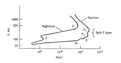
As you are probably aware, solar radiation ionizes atoms and molecules in the atmosphere at altitudes of about 50 km or so and above. The densities of free electrons produced vary from between a billion and a trillion electrons per cubic meter, depending on altitude and time of day (see below).

Different regions of ion density are identified with letters (D, E, F), but the boundaries between regions are not that clearly defined.
To a first approximation, the different ion "layers" can be thought of as kinds of reflecting mirrors for RF, but this really isn't an adequate model to describe why different RF wavelengths are reflected differently.
In general, the reflection of an electromagnetic (i.e. RF) wave at any boundary depends on:
- The permittivities of on either side of the boundary
- The permeabilities on either side of the boundary
- The angle at which the incident wave approaches the boundary
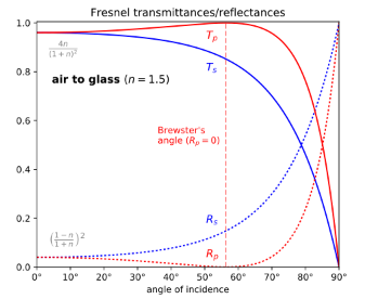
A complete description of how the wave gets reflected is provided by the Fresnel equations, which include expressions for the amount of energy reflected by waves that are polarized perpendicular and parallel with respect to the reflecting medium. An example of the Fresnel reflectance (and transmittance) is shown below for a wave traveling in free space and impinging on glass, with a permittivity 1.5 times that of free space:

Reflection by the ionosphere is more complex because, unlike glass, the reflecting medium has free electrons that are moving and colliding with each other. This causes the permittivity of the ionosphere to vary with frequency. A detailed derivation of why this is so can be found here, but suffice it to say that rather than being constant, the permittivity ($\epsilon$) at any point in the ionosphere is given by:
$$\epsilon = \epsilon_0\left(1 - \frac{f_p^2}{f^2}\right)$$
where $f_p$ is known as the plasma frequency and $\epsilon_0$ is the permittivity of free space. The plasma frequency in turn depends on the local ion densities described above:
$$f_p = \frac{1}{2\pi}\sqrt{\frac{Ne^2}{m_e\epsilon_0}} \approx 9\sqrt{N}$$
where $N$ is the electron density discussed above, $e$ is the electron charge (in Coulombs), and $m_e$ is the electron mass (in kg).
With these models, we can observe a few things:
When $f$ (our operating frequency) is much higher than the plasma frequency at any given layer in the ionosphere, that layer "looks like" free space. Therefore, the wave continues in the direction that it was traveling. At the F layer - the densest layer in terms of electron density - the plasma frequency is around 2 MHz, which would yield an effective permittivity only a small fraction lower than that of free space at 2 meters, but something much different at 80 meters. Recall that it is discontinuity of permittivity or permeability that generally drives reflection of an electromagnetic wave.
When the plasma frequency is greater than the operating frequency, the effective dielectric constant becomes negative. A detailed description of what this implies can be found in the reference linked above, but suffice it to say that this leads to the wave decaying exponentially with distance and never really reaching anywhere.
In between the two extremes meaningful reflection occurs, and is described by the Fresnel equations.
Practical Communications Engineering
In RF communications engineering, the plasma frequency is referred to as the critical frequency. There are a number of other benchmark frequencies that are referred to by the ITU:
Maximum Useable Frequency (MUF)
There are two different types of MUF's that are discussed:
- An "operational" MUF
- A "basic" MUF
The operational MUF that can provide acceptable service given specifics of the RF link (antenna gains, transmit power, receiver sensitivity, etc.)
The basic MUF is the highest frequency by which a radio wave can travel via ionospheric propagation alone, independent of power.
Some definitions of MUF are in terms of the the channel being available over some percentage of the month at a specific time (e.g. 90%). A common rule of thumb is to estimate the MUF at about 3 times the critical frequency.
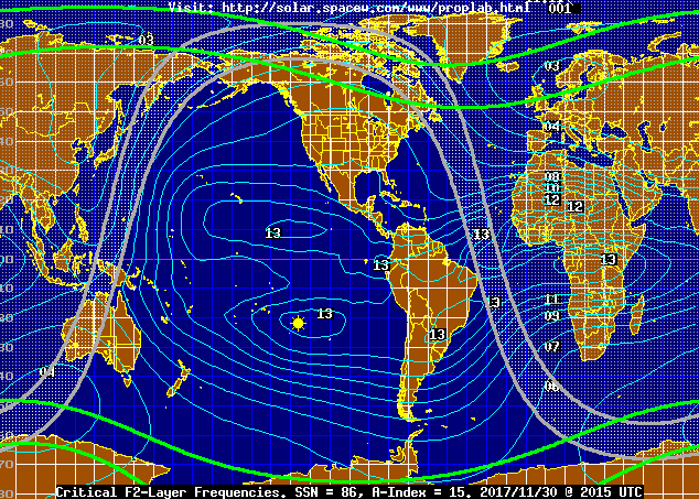
The map below (from spacew.com) shows a contour of F2-layer MUF's (in MHz) by location for the time and date indicated (302015 UTC Nov 2017):

Lowest Useable Frequency (LUF)
The Lowest Useable Frequency for a specified time period is the lowest frequency that can be used for communication on 90% of the days of the month.
Frequency of Optimum Transmission (FOT)
The FOT relates to the availability of a particular geographic path. It is the best working frequency expected to be useable for a specific time (e.g. 2000UTC) for a specified percentage (e.g. 50%) of the days of the month.


