2
$\begingroup$

I'm very interested in replicating a design published by NASA here : https://ntrs.nasa.gov/archive/nasa/casi.ntrs.nasa.gov/19670027843.pdf

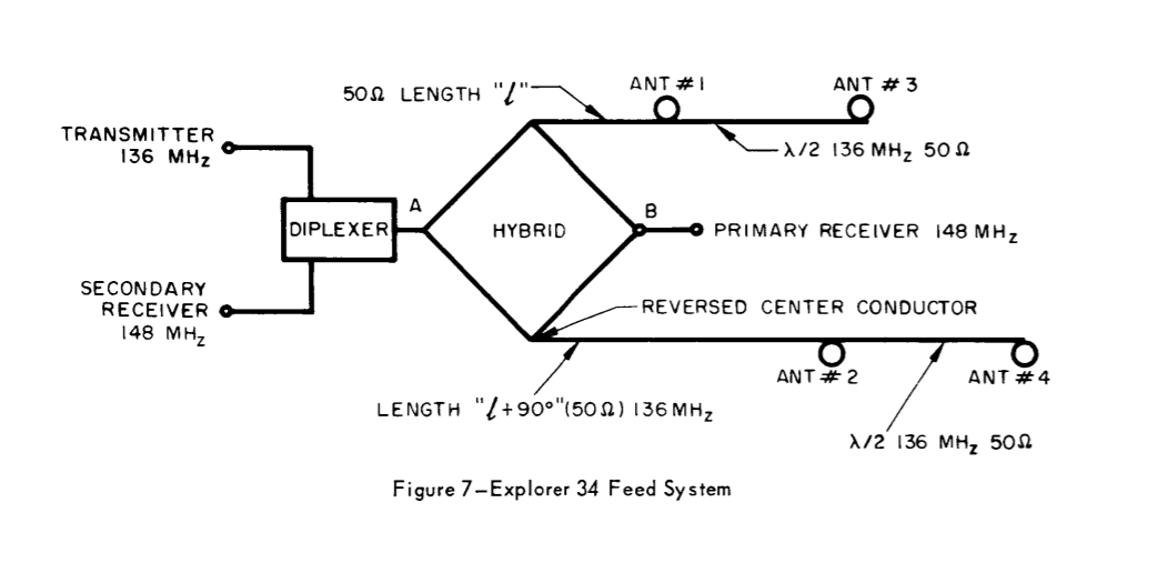
Specifically the arrangement on Page 11. I have a similar design using a hybrid coupler, and this is very nearly what I want to build in terms of antenna system, but I don't understand how the coax is attached to the antenna elements as shown in this diagram. Phasing Network

I would assume that it would simply be the center of the coax, but this doesn't really make sense with the way I understand connecting coax to an element. If someone could explain the connection to the antenna that would be appreciated.

$\endgroup$

2 Answers 2

1
$\begingroup$

It's not stated explicitly in the description for figure 7 (the one from your question), but in the description for a previous and similar design, on page 8:

To get the necessary 90' phase shift, a quarter wavelength of 50 ohm coaxial cable is used on one ouptut. Each antenna is matched to 100 ohms and the opposite pairs are connected by a half wavelength of 50 ohm coaxial cable. This provides an effective impedance of 50 ohms at the hybrid output ports.

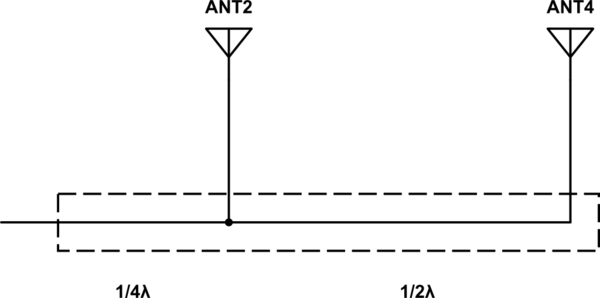
I assume the feedpoint impedance of 100Ω and the half-wavelength 50Ω cable holds, and they are connected like this:

schematic

simulate this circuit – Schematic created using CircuitLab

Arranged this way, the antennas are connected through a simple T-junction power divider.

Each of the antennas is a 100Ω load. If you start looking into ANT4's feedpoint, you see 100Ω. As you move back over the half wavelength of coax, you see 100Ω, but reversed in phase. At this point, ANT2 (also 100Ω) is connected in parallel. 100Ω in parallel with 100Ω makes 50Ω.

$\endgroup$
4
  • $\begingroup$ This configuration would have standing waves on the half-wave section since it is not 100 Ω characteristic impedance, correct? $\endgroup$
    – Kevin Reid AG6YO
    Commented Dec 2, 2016 at 16:32
  • $\begingroup$ @KevinReidAG6YO Yes, though probably not a problem in practice. I can't think of a reason you couldn't use 100Ω coax there, except that it's not readily available. $\endgroup$ Commented Dec 2, 2016 at 16:48
  • $\begingroup$ How can I model this design? I'm attempting to build this in 4nec2 but I'm hitting a bit of a wall trying to create an end fed element. $\endgroup$
    – Kontakt
    Commented Dec 2, 2016 at 18:36
  • $\begingroup$ @KontaktKM4REF Ostensibly the monopoles are mounted on the conductive ground plane of the spacecraft, so that's the other half of the antenna, where the coax ground connects. $\endgroup$ Commented Dec 2, 2016 at 19:54
0
$\begingroup$

It doesn't make much sense to me either, or rather, the details are not specified adequately. What is specified in the document you linked is:

The near quarterwave monopole, fed as one half of an opposed pair of antennas has an input impedance of the order of $80 \pm45^{\circ}$. It is therefore possible to match the impedance to either 50 or 100 ohms depending on system requirements. Usually a plot of impedance vs length of the antennas in the proper structure is made and a convenient value of length selected to facilitate matching. The matching components (all reactive) are installed in a small chamber in the base of each antenna. This permits the rest of the feed system to operate in a low loss balanced condition.

The only “opposed pairs” in this system are the pairs of antennas 180° out of phase, such as the pair of #1 and #3.

Since #3 is (called) a monopole, at the end of a 50 Ω feed line, it must be fed in the manner of a ground-plane antenna, with the spacecraft's outer shell connected as the ground plane.

Then since there is a 50 Ω line to the left and a 50 Ω line to the right of #1, we must conclude that the thing called a matching network in fact incorporates a power divider to split (or combine) the signal between #1 and the line to #3.

I don't find this very plausible, but it's the best interpretation I find so far of what's written there.
$\endgroup$
5
  • $\begingroup$ "near quarterwave monopole, fed as one half of an opposed pair of antennas" Is a direct description of a dipole, unless I'm misunderstanding? $\endgroup$
    – Kontakt
    Commented Dec 2, 2016 at 6:03
  • $\begingroup$ I can only think that they are intending to convey the idea of the monopoles not having co-located feed points as a dipole does. But that is more reason to doubt my description, because what I described doesn't have any impedance dependent on being-a-pair. $\endgroup$
    – Kevin Reid AG6YO
    Commented Dec 2, 2016 at 6:27
  • 2
    $\begingroup$ I'm not so sure about the typographic error assumption. There are no Omegas in the document and all impedance are referred to by measurement unit of ohm. This could very well be just normal complex impedance, written in polar format. $\endgroup$
    – AndrejaKo
    Commented Dec 2, 2016 at 11:40
  • $\begingroup$ @AndrejaKo Ah, I had not thought of that interpretation. That makes some sense and doesn't affect the rest. $\endgroup$
    – Kevin Reid AG6YO
    Commented Dec 2, 2016 at 15:11
  • 1
    $\begingroup$ I think the section you quote only applies to one of the later designs at the end. In that design, they are feeding the two monopoles in a balanced configuration, like they are two halves of a dipole. $\endgroup$ Commented Dec 2, 2016 at 15:35

You must log in to answer this question.

Not the answer you're looking for? Browse other questions tagged .