1
$\begingroup$

I am trying to design and build an antenna + LNA board.

Antenna: http://www.yageo.com/documents/recent/An_FR4_1690_2405_0.pdf

LNA: http://www.avagotech.com/docs/AV02-1237EN

The antenna is specced to run at 168 MHz. In the LNA documentation it provides a suggested circuit for a 500 MHz signal. The suggested circuit is below. My Antenna feeds into the left, and my output is on the right. In building the board following the suggested circuit, only my trace between my antenna and the start of the LNA circuit and the trace between the end of the LNA circuit and my output SMA are 50 ohm traces.
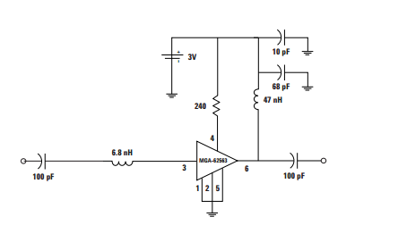
enter image description here

My Question is basically why isn't this working? Am I missing some vital piece of information I have no considered? Given that the circuit is designed for 500 MHz I would expect lesser performance with a 168 MHz signal, however I am unable to pick up any signals.

My test setup consists of an RF generator with an antenna attached, and a network analyzer with this antenna design attached. These two components sit a few feet apart.

I believe all of my soldering connections are correct, and I have confirmed that the board is receiving the appropriate amount of power.

An Image of My board. Dimensions are roughly 1.5"x1.25" and all of my components are 0204 size.
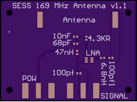
enter image description here

So to recap, I receive no signals on this board even when I am blasting on my RF source right next to it. I have tested other antennas to verify that the broken piece is indeed this new antenna design. Could the mismatch between the frequency used to build the recommended circuit and the frequency my board is running at really eliminate all signals? Or is there some aspect of antenna design that this novice is glossing over?

Any thoughts would be appreciated!

$\endgroup$

2 Answers 2

1
$\begingroup$

Is there any way to independently test the two parts of the circuit -- the antenna and the amplifier? Perhaps use a 1 megaohm through-hole resistor to directly connect your RF source to the big "antenna feed" pad, completely bypassing the antenna, to test the amplifier section?

It appears to me that the version 1.1 circuit board has a ground pour covering most of the board.

While a ground pour is almost always a good thing for almost every PCB, and some board-mount antennas require a ground plane under them to work properly, the ground plane can interfere with a few board-mount antennas.

I don't know enough about antenna design to know just by looking whether a particular antenna must have a ground plane or must not have a ground plane, so I always look at the data sheet.

The data sheet Yageo ANT2405F001R0169A datasheet doesn't specifically say in words anything about a ground plane. It does have a "evaluation board" figure -- I don't see any copper underneath the antenna in that figure, so perhaps this is the kind of antenna that must not have a ground plane under it to work properly?

If this were my board, I would also measure with a multimeter and confirm that all 3 ground pins on the chip are actually connected to ground. Because that's the kind of mistake I often make on the first prototype :-).

p.s.: That datasheet seems to indicate that antenna has a very sharp peak around 169 MHz (one-six-nine). Do you see any difference when you test at one-six-nine vs. one-six-eight?

$\endgroup$
0
$\begingroup$

At 160 Mhz, there are no great problems with lengths of paths, so I'm guessing that is not the problem.

On the other hand, I cannot find any feedthroughs (through holes) to the other side of the board, so you must be sure that all the grounds on the board are connected together. As far as I can see, there are a few areas that don't have connection to others. Are you sure all grounds are connected together? A grounded plane on the other side of the board is nearly always a good idea, even if just used to connect all grounds together.

Did you check if there is a voltage drop on the 240$\Omega$ resistor? If there is no drop, then your LNA isn't consuming any current. If the drop is too large, there might be a short between VCC and ground.

$\endgroup$

You must log in to answer this question.

Not the answer you're looking for? Browse other questions tagged .