2
$\begingroup$

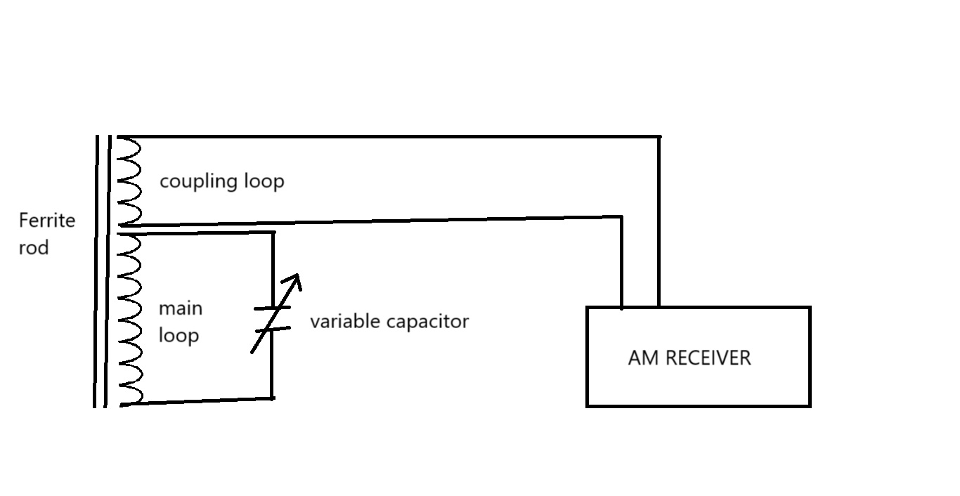
I made a loopstick for my AM radio and I used enameled copper wire of 1 mm (approx) thick to make the loops on a ferrite rod of 1 cm thick and 14 cm long. I made the main loop with the number of turns 4x greater than the coupling loop and that gave a combination of 4:1.

I even tried the combination of 1:1 and 1:2, but none of them work that great.

I also noticed that only a wire greater than 19 (AWG) gives good resonance.

So, I would like to know why the magic is behind using 4:1 and 19 AWG?

I have attached the setup diagram for reference. 4:1 loop stick

$\endgroup$
5
  • 2
    $\begingroup$ Is the radio input a nominal 50 ohm coax or 200 ohm twin line connection? Or are you using the terminals that were connected to an internal loopstick antenna? $\endgroup$
    – tomnexus
    Commented Oct 7 at 20:04
  • $\begingroup$ It has 200 ohm twin line connection. But that's not the point---I need to know whether I made a 4:1 loop stick or it's a 8:1? $\endgroup$
    – user29605
    Commented Oct 9 at 12:51
  • $\begingroup$ No good answers here...so I'll at least comment. Things that would make it work better are larger aperture, better impedance match, and overall longer wire that is closer to resonance. Turns ratio should be moot as long as your tuning capacitor has the right range. Perhaps it doesn't, and the ratio you picked matches the tuning cap better. $\endgroup$
    – user10489
    Commented Oct 10 at 13:51
  • $\begingroup$ I doubt that AWG 19 wire is actually better for receiving. This is probably coincidence, and the real issue is that the way you are winding the AWG 19 is geometrically better, especially if you are overlapping multiple layers which has to be done carefully for best results. But for loopstick antennas, 22AWG - 18AWG is typical anyway. $\endgroup$
    – user10489
    Commented Oct 10 at 13:54
  • $\begingroup$ But that's not a coincidence because I tried with thinner wires too but there is no luck. However, wires thicker than 1 mm works better with fewer turns. BTW, is that a 16:1 ratio loop stick I made? But it works for well for all types of radios that I tested so far, including the RTL SDR. Now, that I can't consider to be a coincidence. 16:1 must be a de-facto standard. $\endgroup$
    – user29605
    Commented Oct 11 at 13:10

1 Answer 1

1
$\begingroup$

A loopstick antenna picks up the signal power from the field when the primary inductor has good resonance. That is, a reasonably high Q of the tuned circuit. In that scenario, the higher winding ratio would help, up to a point where the Q is largely limited by the quality of the inductor itself.

19 AWG wire would provide higher Q than thinner wires, provided that the ferrite material is capable of a high Q at the MW broadcast band. However, there are other possible effects, like how much of the ferrite bar is covered with the windings. Also, the Litz wire is also a way to achieve a higher Q at the high end of the MW broadcast band.

The winding ratio determines the impedance transformation. Your receiver input impedance is 200 ohm, so the "load" seen by the tuned circuit is 3200 ohm. That's high enough not to tax the tuned circuit's Q very much while achieving the impedance match (maximum power delivery) to the receiver.

Another factor is that the loopstick antenna picks up most signal power when the primary inductor is placed near the center of the ferrite bar. So, too many turns of windings may hurt beyond some point.

So, in short, the 4:1 winding ratio is a good place for a receiver impedance of around 200 ohm. Thick wire is advantageous, but a practical trade-off (size, weight, cost) is made with thinner wires in most AM radio construction. In particular, in superheterodyne receivers, the frontend tuned circuit is not the only element contributing to the selectivity (IFTs contribute much more), and the gain is also less important (it's easy to get more gain in the IF stages), so such a trade-off is very often justified. However, what you find is also reasonable when you try to maximize the antenna-frontend performance by itself.
$\endgroup$
4
  • $\begingroup$ i wanted to build a loop stick that will work on all types of AM radio receivers. That's why I thought of using 19 AWG wire with 4:1 turn ratio for maximum performance. However, this loop stick can be used with many types of AM receivers only because of the variable capacitor. Otherwise, it would have a static resonance. So, if the variable cap is helping to match with all types of AM receivers, does that mean that a variable capacitor can help adjust the impedance too? $\endgroup$
    – user29605
    Commented Oct 12 at 11:31
  • $\begingroup$ No. Tuning the circuit's resonance is a separate matter from matching the impedance. $\endgroup$ Commented Oct 12 at 19:33
  • $\begingroup$ Good answer. I've seen papers that describe in detail exactly how to wind it so that the ideal amount of the stick and each layer of windings is exposed to maximize reception. $\endgroup$
    – user10489
    Commented Oct 13 at 14:58
  • $\begingroup$ Whatever, but I came to know that 16:1 loop stick works best using 19 AWG. I tried it practically with many types of ratio turns and wire gauge but only 16:1 works pretty well on most radios. $\endgroup$
    – user29605
    Commented Oct 14 at 13:53

You must log in to answer this question.