3
$\begingroup$

My understanding is that the ground plane radials used on, for example, a free standing 5/8 wave 10 m vertical antenna mounted on a metal pole, are actually 1/4 wave length decoupling stubs, the function of which is to present a high impedance at the frequency being used to isolate in an RF sense the metal mounting pole from the antenna and stop the pole from becoming part of the antenna and radiating / receiving.

Whether this is true or not, can i use the decoupling stub idea to enable a 10 m vertical yagi to be mounted on a metal pole with the pole in between the elements and not have the metal pole upset the operation / radiation pattern / impedance of the yagi ?

If anyone knows about this, any chance of getting details on construction or pointing in the right direction for more information ?
$\endgroup$
8
  • $\begingroup$ Have you performed any measurements to be sure you need to modify the pole? It's possible any change is tolerable and/or very difficult/expensive to correct. $\endgroup$
    – Brian K1LI
    Commented Apr 26, 2020 at 17:59
  • $\begingroup$ @BrianK1LI, this is exactly what i have been trying to figure out, i haven't performed any tests myself directly, no one seems to know what difference a metal pole will make, but it seems to me common sense that it will mess up the impedance and pattern at least a bit. If it were true that using a metal pole makes little or negligible difference or removing the effect of the metal pole is just not worth the effort then i would be happy with that and then mount my 10 m vertical yagi directly in a metal pole. $\endgroup$
    – Andrew
    Commented Apr 28, 2020 at 5:24
  • $\begingroup$ Based on little change of the feedpoint impedance of the driven dipole in my answer, below, simulation indicates that the pole may not be a problem. It is, at least, worth a try without modification. $\endgroup$
    – Brian K1LI
    Commented Apr 28, 2020 at 11:01
  • $\begingroup$ @BrianK1LI Brian do you mean that it's worth a try using a metal pole without breaking it up or using decoupling stubs ? If i were to construct a 6 element yagi then the pole could be possibly be between directors 2 and 3 which is away from the driven element and then hopefully will affect antenna performance less ... $\endgroup$
    – Andrew
    Commented Apr 29, 2020 at 0:02
  • 1
    $\begingroup$ I scaled the 5-element yagi example with EZNEC and placed a 1-wavelength, 2" diameter pole halfway along the boom, connected to a MININEC ground. It strongly affected the feedpoint impedance and very adversely affected the F/B. $\endgroup$
    – Brian K1LI
    Commented Apr 29, 2020 at 0:32

5 Answers 5

4
$\begingroup$

RE: ...understanding...that...ground plane radials are...used to isolate...the metal mounting pole from the antenna and stop the pole from becoming part of the antenna and radiating / receiving.

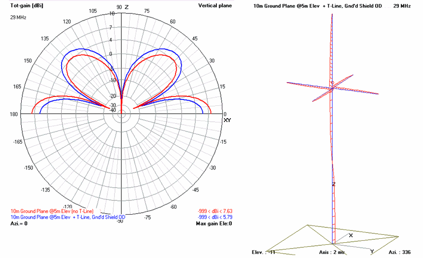
Unfortunately (for an example), even a set of 4 x 1/4WL radials of a 1/4WL v-pol "Ground Plane" antenna does not prevent r-f current from flowing along the outer diameter of the outer conductor/shield of coaxial transmission line connecting it to the source (the transmitter), even though the coax shield outer conductor is connected to and at the surface of the Earth.

R-F current flowing along the coax shield OD (and/or the OD of a metallic tower/pole etc used to support the antenna) produces e-m radiation into space just as it does when flowing along the vertical conductor of the ground plane antenna, itself.

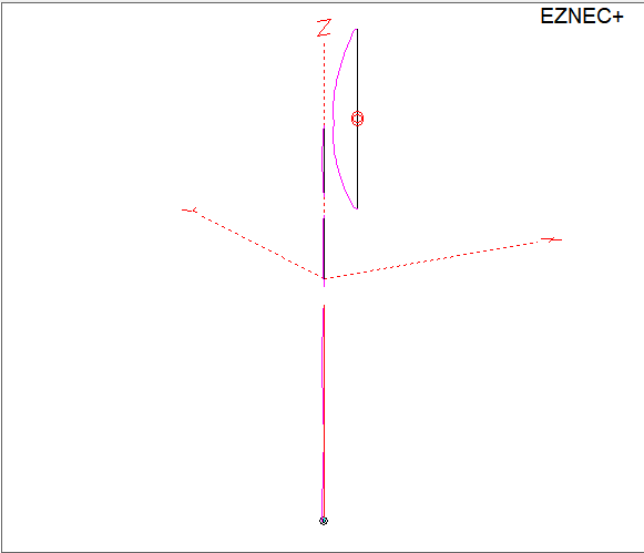
The following NEC4.2 analysis is an illustration of this. The red lines surrounding the wire model at the right side of the graphic show the relative amplitude and phase of the r-f currents flowing along those conductors.

enter image description here

$\endgroup$
3
$\begingroup$

I modeled a $\frac{\lambda}{2}$ vertical dipole located $\frac{\lambda}{10}$ from the top of a grounded $\lambda$ conductive pole. Numerous NEC2 simulations with four (4) $\frac{\lambda}{4}$ and $\frac{\lambda}{2}$ radials at locations up and down the conductive support did meaningfully reduce currents in the support.

Reducing currents in the conductive pole requires breaking it up into lengths that won't support current at the operating frequency. Shown below is the first example that showed meaningful current reduction, requiring the pole to be broken into three sections.

enter image description here

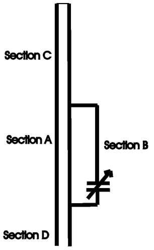
Each of the upper sections is $\frac{\lambda}{5}$ long and they are separated by $\frac{\lambda}{20}$, but the separation was just for convenience in simulation. This can be accomplished with insulators, of course, but also using de-tuning "loops" a la W8JI and others:

enter image description here

Maximizing the current through the capacitor-tuned loop sections A and B minimizes the currents in the adjacent sections C and D.

$\endgroup$
3
$\begingroup$

The radials are there to present a low impedance, not a high one. The idea is to make the radials the lowest impedance thing around, though whether that's true or not depends on the mast, feedline, and other environmental factors beyond the antenna designer's control.

Mounting a vertical Yagi on a vertical mast is necessarily going to alter the antenna's behavior since the mast is essentially an additional element. You will want to minimize the interaction between the antenna and the mast since the contribution of the mast to the radiation pattern will probably not be a desirable one.

The other answers have demonstrated some models which show potential scenarios. It's tempting to overgeneralize these results, but keep in mind the way the antenna interacts with the mast is highly dependent on the geometry between the two. You'll have to model or empirically evaluate your specific situation to know what can work.

Unfortunately the only sure way to minimize interaction between the antenna and the boom is to get them apart, either through a horizontal member or a non-conductive one.

$\endgroup$
2
$\begingroup$

Modeling indicates that there are two steps you can take to reduce the interaction between the antenna and a conductive support:

  1. Remove the conductive portion of the support from the space between the elements
  2. Insulate the support from ground

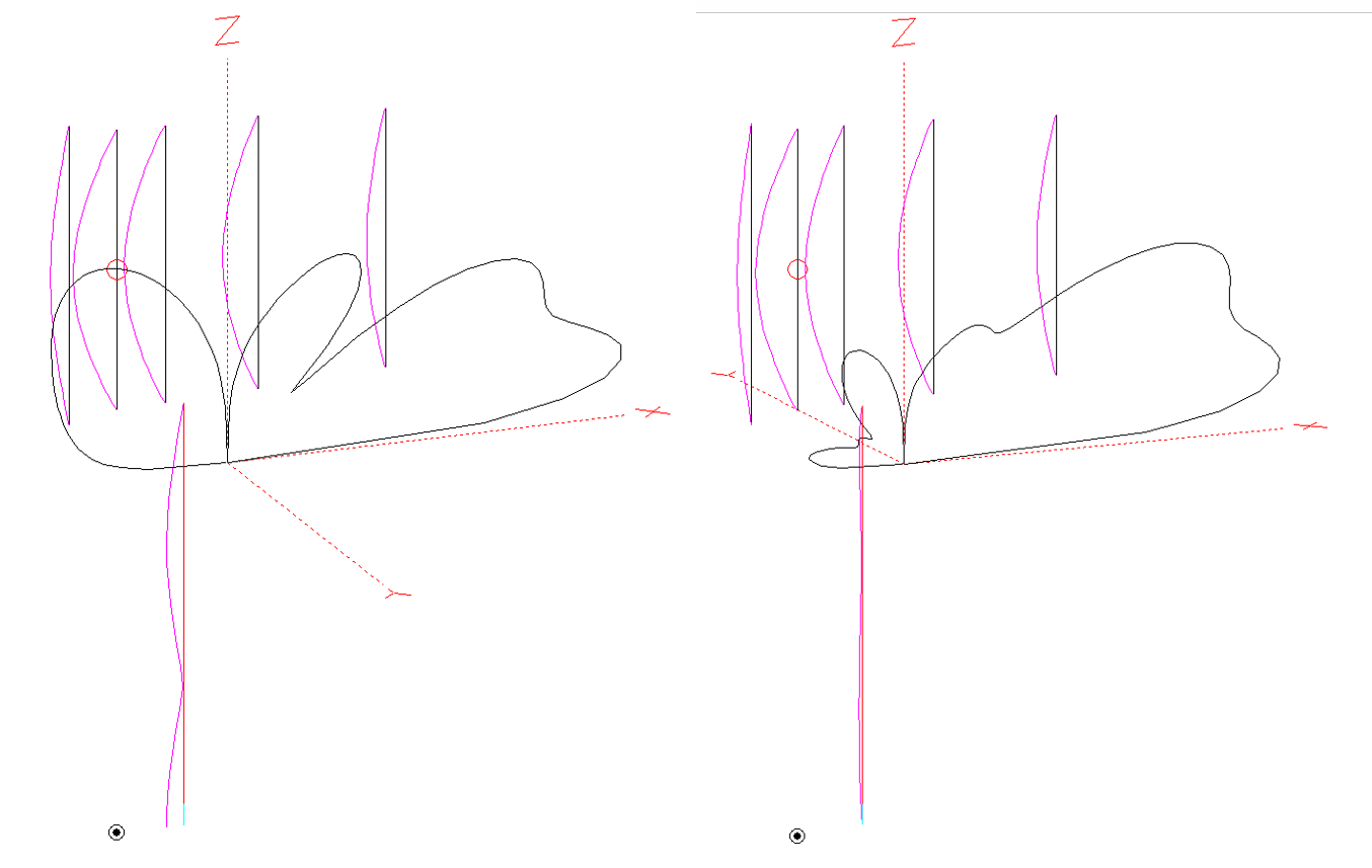
The image on the left, below, has a conductive element connected to ground; the image on the right does not. Note the substantial current in the support on the left and the near absence of current in the support on the right. The vertical radiation pattern from the antenna on the right loses about 0.25-dB of gain and about 2-dB of F/B compared to the same antenna without the support.

enter image description here

Note that simply insulating a "full length" support from ground does not provide any relief, nor does it suffice to insulate a top section of metallic support from a bottom section.

$\endgroup$
4
  • 2
    $\begingroup$ Do these conclusions hold for all cases or are they very specific to the mast length selected in the model? $\endgroup$ Commented Apr 29, 2020 at 14:55
  • $\begingroup$ @PhilFrost-W8II I expected a half-wave mast to be the worst, but it shows no current with: the boom at 1 wavelength above ground; the conductive mast protruding a half-wave toward the boom from the ground; regardless of whether the mast is grounded or insulated. $\endgroup$
    – Brian K1LI
    Commented Apr 29, 2020 at 18:03
  • $\begingroup$ @BrianK1LI Let's assume that i were to use a metal pole going up to the boom of a 5 element vertical yagi so the pole is between the lower halves of director 1 and director 2, then can you suggest a mast length that would minimize the effect the pole has on the antenna impedance and radiation pattern ? Also would it help if the yagi is offset from the pole so that the pole isn't directly in line with the elements ? $\endgroup$
    – Andrew
    Commented Apr 30, 2020 at 9:26
  • $\begingroup$ @Andrew I don't have time to perform an exhaustive study of this subject. I do see that a grounded mast which reaches boom height must be offset >~0.1-wavelength, more for the same mast not grounded. This is all the time I have to devote to this question. There may be combinations of boom height, positions of elements w.r.t. the mast and mast offset that would work better. I recommend AutoEZ to automate an analysis. $\endgroup$
    – Brian K1LI
    Commented Apr 30, 2020 at 12:32
0
$\begingroup$

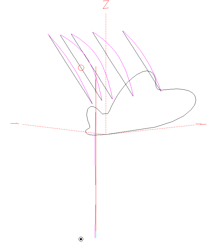
Here is some out-of-the-box thinking: rotate the yagi elements 45$^o$:

enter image description here

The interaction with the (grounded) mast is virtually eliminated, plus the ground-reflection gain at least partially compensates for any polarization loss you might experience.

$\endgroup$

You must log in to answer this question.

Not the answer you're looking for? Browse other questions tagged .