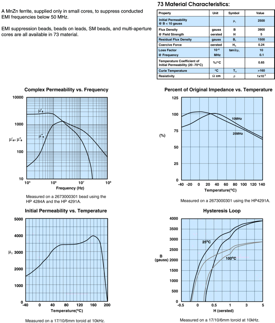
For the purposes of amateur radio, ferrite materials are usually useful for making inductors where an air-core coil could not feasibly achieve the necessary inductance. Three relevant questions which the datasheet can answer for us are:
- what inductance will a coil on this core have?
- what losses will this core material introduce?
- at what current will this inductor saturate?
To know what inductance our coil will have, we need to know the permeability of the core material. The complete equations to calculate inductance are complex and depend on the geometry (E-I, toroid, wire gauge, turn spacing, number of turns, ...) of the inductor, but it all cases, higher permeability means more inductance per turn of wire.
The first, and simplest measure of permeability is in the table, under initial permeability. This table doesn't specify units, but it could be gauss/oersted or G/Oe, which are CGS units. The nice thing about G/Oe is that the permeability of air or vacuum (conventional symbol: $\mu_0$) is 1G/Oe, so permeability in G/Oe is also relative permeability, which is usually what inductance calculators expect. This is not true when using SI units, where $\mu_0 = 4\pi\cdot10^{−7}\:\mathrm{H/m}$.
However, the permeability of ferrite is not linear. Due to its physical properties, the permeability effectively drops with frequency. The picture is further complicated at high frequencies because it takes some time for the core to magnetize, so at high frequencies, the magnetic flux density (B) might lag significantly behind the magnetizing field (H). From the perspective of the electrical circuit, this looks like higher losses in the form of a series resistance, and reduced inductance.
We can break this "lag" into in-phase and out-of-phase components, and it becomes a complex number. The first graph, Complex Permeability shows this. , $\mu'_s$ is the in-phase part of permeability, the part that makes inductance. $\mu''_s$ is the out-of-phase part of permeability, the part that makes losses. This is very similar to how we might represent impedance, with one part being reactance (capacitance or inductance) and the other part being resistance.
The ratio $\mu''/\mu'$ is also the ratio of energy lost vs. energy stored in the inductor. This quantity is called the loss tangent, and is also written as $\tan \delta$. It is also the reciprocal of the quality factor $Q$. If you've calculated or measured the inductance $L$, you can also calculate the equivalent series resistance:
$$ \tan \delta
= \frac{\mu''}{\mu'}
= \frac{1}{Q}
= \frac{R_\text{ESR}}{2\pi f L} $$
A related parameter, loss factor, is expressed in the table. This is simply the loss tangent, divided by the initial permeability. It is done this way because including an air gap in the core reduces the loss tangent at the expense of decreasing the permeability. Note that the loss factor in the table is specified for a low frequency; at high frequencies $\tan \delta$ increases significantly and you will have to calculate the loss factor for yourself from the graph.
The last concern we have is core saturation. This one is pretty easy if we can assume all the magnetic flux is inside the ferrite. For inductors wound on closed shapes like toroids or E-I cores, this is reasonable. There's an entry in the table: Flux Density @ Field Strength. This is where this material saturates. It can also be determined graphically from the Hysteresis Loop: the point where the two black lines meet at the upper-right is saturation.
All we have to do is translate between current in the coil around the core and field strength. This is pretty easy if we convert oerstead to the equivalent SI unit: ampere/meter:
$$ 1 \mathrm{Oe}
= {1000 \:\mathrm A \over 4 \pi \:\mathrm m}
\approx 79.58 \: \mathrm A / \mathrm m $$
Here, ampere might more intuitively be called an ampere-turn. They are the same thing dimensionally. The "per meter" part refers to the nominal length of the magnetic circuit: for example, the circumference of a toroidal core. So for example, say we have a toroidal core with a circumference of 4cm, with 10 turns on it, with 500mA. The field strength is then:
$$ \begin{align}
\frac{10 \cdot 0.5 \:\mathrm A}{0.04 \:\mathrm m} &= 125\:A/\mathrm m \\
125\: \mathrm A/ \mathrm m \cdot \frac{4 \pi}{1000} &\approx 1.57\: \mathrm{Oe}
\end{align} $$
This is less than the 5 Oe in the datasheet, so the core is not saturated.
