7
$\begingroup$

People often say common-mode current flows on the outside of the shield, while the current on the inside of the shield is always opposed by an equal but opposite current on the center conductor. This is because skin effect separates the inside and outside of the shield.

But if skin effect is isolating the inside and the outside of the shield, why would the inside-shield and center-conductor currents always be equal but opposite? If skin effect makes the inside and outside of the shield distinct, why can't there be a common-mode current on the inside?

$\endgroup$
2
  • 1
    $\begingroup$ Spitballing here, but don't currents on the inside induce their own opposites in the shield, Faraday cage–style? $\endgroup$ Commented Nov 20, 2017 at 18:47
  • 1
    $\begingroup$ There is some insight here. A common mode current inside the coax will produce a net EMF around the shield, which is a short circuit. Still not a proper answer. $\endgroup$
    – Juancho
    Commented Nov 22, 2017 at 19:31

4 Answers 4

6
$\begingroup$

It is helpful to understand the basic functioning of a coaxial cable. But first there are two important phenomenons that must be understood in order to proceed.

Skin Effect

When direct current (time invariant current) passes through a conductor it tends to uniformly use the entire cross sectional area of the conductor. When alternating current (time variant current) passes through a conducting material, it has a tendency to concentrate the current near the surfaces of the conductor. The occurs due to the changing direction of the magnetic field associated with the alternating current resulting in a back electromotive force that tends to push the conducting electrons towards the surface of the conducting material. As the frequency of the alternating current is increased, the crowding toward the surface becomes more pronounced. Since there is less conducting area, the resistance rises with frequency.

In a common conductor such as copper, the skin effect can be quite pronounced at typical amateur radio frequencies. For example, at 1 MHz, 63% of the current flows in the outer ~0.067 mm of a round copper wire. The current decreases exponentially and this 63% level is considered one skin depth. 98% of the current is contained in four skin depths (0.298 mm) from the surface of the wire. Past five skin depths, there is for all practical purposes no current flowing in the wire. Thus the center of the wire with a radius greater than five skin depths is essentially wasted material and can be removed (making a tubular shape) or replaced with other structural materials. We see the latter in amateur radio circles in the CopperWeld® brand of wire where the inner material is steel (for strength purposes) but with an outer copper coating (for RF purposes). If the thickness of the copper coating is at least 5 skin depths for the frequency in use, the RF current will never "see" the higher resistance steel core due to the skin effect.

Proximity Effect

When alternating current flows through a conductor and this conductor is in close proximity to another conductor carrying alternating current, the current in the conductors will tend to be crowded into smaller regions of the conductor resulting in increased resistance. It is important to note that this is in addition to the skin effect. Thus the proximity effect tends to further increase the effective resistance of the conductor beyond that of the skin effect alone.

If the two wires are carrying current in opposite directions, the crowding tends to occur on the surfaces of the wire that are closer together. If the current is flowing in the same direction, the crowding tends to occur on the surfaces that are further apart.

Coax Cable

Now consider a coax cable with an outer shield that is several skin depths thick and with an alternating current flowing only on the inner (center) conductor. The shield is completely disconnected for this description. The alternating current flowing in the center conductor develops a magnetic field around it. Since the outer shield conductor is several skin depths thick, there is practically no magnetic field developed within the outer conductor.

We can apply Ampere's Law to determine that the magnetic field of the inner conductor will induce an equal and opposite current on the inside of the outer shield (this is a working example the proximity effect). The current on the inside of the outer conductor must close on itself so that the current flowing on the outside of the shield is the same as the current flowing on the inside of the shield.

Now if we connect the shield as it would be used in the usual condition for an amateur radio application, we have current flowing on the outside of the shield (due to skin effect) that is fully cancelled out due to the opposite induced current from the inner conductor described earlier. This leaves us with only the current on the inside of the outer conductor. It should be clear from this description that the result of the current flowing only on the inside of the outer conductor is therefore a result of both the skin effect and the proximity effect.

The net result is that the shield of the coax cable acts as an electrostatic shield that, for all practical purposes, does not allow the electromagnetic energy to radiate from the coax cable.

Common Mode Current on Coaxial Cable

If we now bring another conductor carrying an alternating current (such as an antenna element) in close proximity to the coax, it will induce a current in the shield. If the shield is several skin depths thick, none of this induced current will appear on the inside of the shield conductor (or anywhere else inside the coaxial cable) but rather it will flow on the outside of the shield due to skin effect.

In this condition, we have two unique currents flowing on the shield of the coax – the current flowing on the inside of the shield that is generated by the transmitter connected to the coax as well as the current that is flowing on the outside of the shield due to magnetic coupling from the antenna. With sufficient thickness of the shield, these two currents do not “see” each other since neither will (effectively) pass through the center of the shield to interact with the other. This is quite different from say the reflected current that occurs due to a mismatched load where the forward and reflected currents do “see” each other and interact to create a standing current wave.

Since the two currents have no interaction along the length of the coax it is, for all practical purposes, as if they are traveling on separate wires. Thus when describing coaxial common mode current, the exterior of the shield is often described as the “third wire” of the coaxial cable. Of course this is simply a simile but it closely fits the observable characteristics.
$\endgroup$
3
$\begingroup$

First, does it matter where the common-mode currents flow? Coax works as a transmission line because the (ideally) equal but opposite currents on the center and shield create opposite fields which exactly cancel for points outside the cable. Thus, it does not radiate. And by reciprocity, external interference is rejected.

The same concept is in play with twin-lead transmission lines: the equal and opposite current cancel. No skin effect required.

Skin effect does not make the inside and the outside of the shield function as distinct conductors. Think about the contradictions this would make: how does current "know" if it should flow on the inside or the outside? How would open transmission line stubs work if the shield current on the inside "wrapped around" and traveled back on the outside upon reaching the end of the coax? How could twin-lead choke baluns work?


There's a phenomenon similar to skin effect called proximity effect. It's relevant to transformers and twin-lead, or any application where two or more conductors in proximity are carrying RF current.

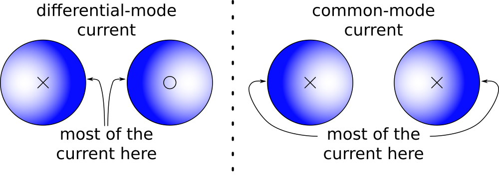
When two conductors are carrying currents in opposite directions (differential-mode), the current density is highest in the regions closest to the other conductor. When the current is in the same direction (common-mode), current density is highest in the regions farthest apart.

enter image description here

Both skin and proximity effects arise due to eddy currents. Skin effect is a special case when there's just one conductor, with the current density trying to get as far away as possible from all the other parts of the conductor trying to carry current in the same direction.

So in the case of coax, for a common-mode current the current density will be highest on the outside of the shield since that's the farthest point away from all the other points in the coax.

For a differential-mode current the current density is highest on the inner surface of the shield and the outer surface of the center since that's the closest points between the two.

enter image description here

This isn't skin effect creating a magic barrier between the inside and outside of the shield. It's eddy currents reinforcing some currents while cancelling others. It's the same underlying physics as skin effect, but there's no magic barrier. The inside and outside of the shield are not "distinct conductors".

And that the current density is highest on the outside of the shield isn't relevant for most purposes. It's cancellation of fields, not magic skin effect barriers that are responsible for making our coax not radiate.

$\endgroup$
1
  • $\begingroup$ Comments are not for extended discussion; this conversation has been moved to chat. $\endgroup$ Commented Dec 1, 2017 at 19:25
0
$\begingroup$

The statement "common-mode current flows on the outside of the shield" is true for a perfect shield. A low cost 60 ohm TV cable might have some common-mode current on the inside. Look at it the other way, Inject a common-mode current on the coax by use of a toroid transformer and measure the voltage between screen and inner conductor at the cable end. A perfect cable (Flexwell with 0.5 mm wall thickness copper tube for the screen) would not show any signal at all, but a low cost TV coax might show something like 60 dB below the coupling to an un-screened wire.

  • leif -
$\endgroup$
3
  • $\begingroup$ Even a perfect shield would have common-mode currents on the outside, if it was feeding a dipole without a common-mode choke. $\endgroup$ Commented Nov 22, 2017 at 0:02
  • $\begingroup$ @MikeWaters Isn't a CF dipole normally a balanced load? $\endgroup$
    – Glenn W9IQ
    Commented Nov 24, 2017 at 12:38
  • $\begingroup$ @GlennW9IQ Thanks for catching that! Comment modified. $\endgroup$ Commented Nov 24, 2017 at 15:11
0
$\begingroup$

The name "common mode" means that the current on the shield and the center conductor is traveling in a common direction. This condition is a violation of the assumptions required to make a transmission line work.

For the transmission line to work correctly, the current must be in opposite directions on the shield and center conductor; in this case, the current will be on the inside of the shield and the outside of the center conductor, the induced magnetic fields will oppose and cancel, and there will be no leakage.

If there is common mode current, then these conditions are violated, and there will be RF leakage both into and out of the transmission line.

The world generally not being perfect, it is possible for both conditions to exist simultaneously. In other words, you can have both common mode current and opposing current on the shield at the same time. When this occurs, then presumably the common mode current will be on the outside of the shield and the opposing current on the inside of the shield and the portion of the current that is common mode will cause leakage. However, it would also be possible (but unlikely--so maybe only a small fraction of the current) for the common mode current to travel in other parts of the shield and cause eddy currents, which would heat the shield rather than leak. Poor quality coax might have a thin shield, which be less than the skin depth, allowing the two currents to mix and allowing eddy currents to be worse.

Typically, common mode current in transmission line is caused by the shield of the coax coupling with the antenna, so that matched opposing currents flow in the antenna and the outside of the shield in addition to the matching currents on the inside of the shield and the outside of the center conductor. This coupling essentially makes the shield part of the antenna.

$\endgroup$

You must log in to answer this question.

Not the answer you're looking for? Browse other questions tagged .