Short answer: No, and in fact you'll often get more bang for your buck by avoiding coaxial baluns.
The description of the balun's purpose in an antenna system you quote is an oft repeated bit of "common wisdom" in ham radio, but it is such an over-simplification that it is at best drastically misleading and at worst, just plain wrong.
The purpose of a balun in an antenna system is to suppress common mode current. That's it. You can (and should) use them on balanced line, even when feeding it with a balanced tuner. You can (and should) use them on balanced, resonant antennas like dipoles that are fed with unbalanced feedline, even if the SWR is perfect. You can (and should) use them between an unbalanced vertical antenna and a coaxial feedline. (A side note: Virtually every ham radio antenna system should have some form of common mode suppression mechanism installed, regardless of antenna or feedline type).
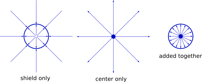
The coax shield behaves as two (mostly) independent conductors. The center conductor of the coax is "driven" by the radio, while the shield is held at ground potential. Because the coax shield has a non-zero impedance (there's some amount of resistance and reactance present, because thermodynamics), and because the inner layer of the shield is strongly coupled both inductively and capacitively to the center conductor, a current is induced on the inside of the coax shield that is, in theory, equal in magnitude and opposite in phase to the current on the center conductor.
These two fields exist in close proximity and we hope they are precise opposites of each other, so the two fields effectively cancel each other out, preventing the feedline from radiating. This pervasive idea that the coax shield behaves as a grounded Faraday cage is just flat out wrong. Faraday cages do not work in the near field, and the shield is most DEFINITELY in the near field of the center conductor. Also, there has to be a return path, so the shield must carry some amount of current.
Notice that when I mentioned the cancellation of the two opposite fields, I specifically stated that the current was flowing on the inside of the coax shield. This is because skin effect causes the inside and the outside surfaces of the shield to behave as two separate conductors, connected to each other through a relatively high impedance resistor. Exactly how high the impedance of said virtual resistor is depends on the electrical and physical characteristics of the feedline, such as characteristic impedance, capacitance, length relative to frequency, and many other variables.
In an ideal world, the outside of the coax shield would have a nearly infinite impedance between it and the inner coax shield. This is because any current flowing on the outside of the coax shield cannot interact very efficiently with the current flowing on the center conductor of the coax, meaning that the field generated by the current flowing on the outside of the coax shield is not cancelled out by any other fields. Any current flowing on the outside of the shield is free to radiate.
This also means that any current induced on the outside of the coax shield from external sources, such as a noisy appliance power supply in your home, will be free to travel back to your radio, where it will induce current on the chassis of the radio. A significant fraction of complaints about RF noise received from within the ham's own home can be tracked back to common mode currents entering the receiver via the coax shield.
Now that we know that a coax cable behaves more like 3 conductors, not 2, let's look at how that works with a coaxial balun.
If we take a few feet of coax and wrap it around a ferrite toroid, the fields generated by the center conductor and the inside of the coax shield are still cancelling out, nothing much has changed inside the coax. They're still in very close proximity, and Ohm's Law says that if the current is going out through the center conductor, some of it has to be coming back in via the coax shield. However, we have suddenly put the outside of the coax shield in very close proximity to the ferrite toroid, and there is no opposing field to cancel the field generated by the current on the outside of the coax. Any current flowing there will couple to the toroid, primarily inductively, and a magnetic field (and current) will then be induced on the toroid. It becomes an electromagnet. If the toroid happens to be very good at turning energy at the frequency that's passing through the coax in to heat, then much of the current flowing on the outside of the coax will turn to heat rather than making it back to the radio, or out to the antenna, while anything flowing on the inside of the coax shield or the center conductor continues on mostly unaffected.
There are some problems with using coax for toroid baluns. The two biggest are:
Coax doesn't like to make sharp bends, so larger loops have to be made, resulting in less inductive coupling. This usually means you have to use several toroids stacked together, and a significant length of coax.
Coax isn't very good at dissipating heat. This means that if the toroid is turning lots of common mode current in to heat to get rid of it, and you've covered up most of the toroid's surface area with coax, things could get quite hot, potentially hot enough to damage the coax.
Coax baluns that don't use toroids or iron cores cannot provide sufficient common mode suppression on multiple bands, particularly if the antenna has a high impedance or poor match on one or more bands. You should be aiming for a bare minimum of 1,000 ohms of common mode impedance (>2,000 is best), but air core "ugly baluns" typically struggle to achieve more than 500 ohms even on their designed band. On other bands, it can be even lower. The characteristic capacitance of the coax causes an ugly balun to behave like a resonant band reject filter from the common mode current's perspective, not like a broadband choke.
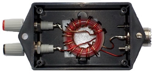
So the problem is not that there is current on the outside of the coax shield, the problem is that the current on the outside of the coax shield is unopposed. If we were to solder two wires to a bit of coax, one to the shield and one to the center conductor, then wrap those two wires around a ferrite toroid as your image shows, the current on the two wires interact with the toroid about equally. If the two wires were carrying unequal currents, they wouldn't cancel exactly, and a magnetic field would be induced in the toroid. By selecting materials that are very lossy at the frequency of interest, the balun can be used to dissipate only the portion of the current that is unopposed. If 10 watts were flowing on the center conductor, but only 8 watts were flowing on the shield in total, a field equivalent to 2 watts would be induced on the toroid and turned in to heat. At that point the current on the two wires is once again balanced, and no current will appear on the coax shield, because there is no unopposed component remaining.
Imbalance in antenna systems is virtually universal. They are designed to radiate, which means they must, by their nature, couple heavily to their nearby environment. This inevitably means that the antenna system will be prone to picking up local common mode noise, as well as generating common mode current due to asymmetry in the antenna system. A balun is a way to ensure that the current on the two conductors is equal and opposite, nothing more or less.
Wire baluns have their own set of challenges, mostly heat related:
- Toroids are even worse than coax at dissipating heat. If you want good choking in a coaxial balun, you'll need multiple toroids, meaning more surface area and more mass to handle waste heat. With a wire balun, it is quite possible to get excellent choking impedance from a single large toroid, but the same amount of power is dissipated, meaning that the toroids can become very hot. A single core, wire balun should not be used for more than 250 watts unless you can see with a fairly good degree of certainty that your system is not generating excessive common mode currents.

