2
$\begingroup$

This is a sort of follow-on question from my tuners in series question.

The problem I am ultimately trying to solve is this:

I am using a manufactured end-fed, half-wave 40m antenna. The manufacturer claims a certain SWR at several frequencies and I am trying to get my actual SWR closer to what the manufacturer claims is possible.

I realize that my conditions won't match the manufacturer's conditions but if I can receive some overall, general guidance on what I can/should do, it would be very much appreciated.

The antenna is horizontal, approximately 19 feet above ground, fed by a 100 foot RG-58X feedline.

As you can see from this spreadsheet, my SWR is consistently higher (with one very odd exception in the 12m band!).

The manufacturer used a RigExpert AA-30 for SWR readings, I used a RigExpert AA-54.

(The 2.85 SWR I measured was drifting between 2.8 and 2.9 so I used the average value).
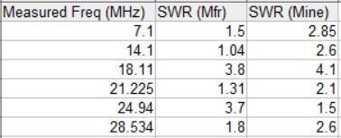
Chart of my SWR vs. the manufacturer's SWR

$\endgroup$
3
  • 2
    $\begingroup$ It would help to know more precisely what this antenna is. Pictures, links to product pages, etc. $\endgroup$ Commented Jul 9, 2017 at 18:14
  • $\begingroup$ I appreciate that but I am trying to avoid any potential bad-mouthing of the manufacturer or laying unintentional blame on the manufacturer when the fault is most likely my own. $\endgroup$
    – Steve
    Commented Jul 9, 2017 at 18:42
  • 3
    $\begingroup$ @Steve but that's really not in your interest here. Really, it's like calling your car mechanic, saying you might be in need of a replacement exhaust, not sure, but when asked for the make of your car, you answer "sorry, don't want to shame the car manufacturer". At least post a picture of your setup! $\endgroup$ Commented Jul 9, 2017 at 21:07

3 Answers 3

4
$\begingroup$

End feed antennas present a very unique challenge when it comes to comparing results and metrics. Despite a lot of erroneous information on the web, an end feed antenna requires a counterpoise of some type.

If you do not provide a very purposeful counterpoise of sufficient length, the antenna will use the shield of your coax as the counterpoise regardless of any unun, balun, or choke that has been installed.

Now consider how many different ways one can place the coax in an antenna installation. Some hang it in the air, some run it partially on the ground, some bury it, some run it next to gutters, some coil it up, some use long lengths of coax, some use short lengths of coax, etc. But in all of these cases, the coax is part of the radiating and receiving antenna. It should come as no surprise then when one installation cannot duplicate that of another!

And then even if you provide a purposeful counterpoise, how many of these are of unspecified length and run out onto the ground from varying heights? Again, no basis for comparison.

You should work on optimizing your installation. In general, more height is better. Experiment with a good choking balun on your coax and a purposeful counterpoise of various lengths in various orientations. With end feds, it is primarily a cut and try process.

And one final thought. If your coax is part of the radiating antenna, inserting an SWR bridge or antennalyzer will actually change the tuning of the antenna slightly. It can be a very frustrating cat and mouse game.

$\endgroup$
3
  • $\begingroup$ Very interesting. Hmmm a counterpoise... Its worth a shot! $\endgroup$
    – Steve
    Commented Jul 10, 2017 at 1:22
  • 1
    $\begingroup$ J-pole aka end fed zepp does not need a counterpoise. A broad generalization like you have made is probably wrong. $\endgroup$
    – user10489
    Commented Aug 16, 2018 at 0:57
  • $\begingroup$ @user10489 The end fed Zepp and the J pole both suffer from common mode currents as they a both severely unbalanced. The Zepp designation typically refers to an end fed 1/2 wavelength fed with balanced line. Other than the type of feedline, there is no difference in the need for a counterpoise compared to so called EFHW. $\endgroup$
    – Glenn W9IQ
    Commented Aug 16, 2018 at 5:19
2
$\begingroup$

As Glenn says, common-mode current may be an issue. So, a first step would be seeing where the currents are going: How to detect common-mode currents or “RF in the shack”?

A more mundane explanation: the antenna is simply out of tune. Plotting SWR over frequency you should be able to determine if the antenna is simply too long or too short.

I'd also note that 19 feet up for a 40 meter antenna is not very high. See how antenna height determines the radiation pattern. Besides the negative impact to antenna efficiency, that proximity to the ground will perturb the fields around the antenna, which could explain the discrepancy with the manufacturer's numbers.

Finally, it's entirely possible the antenna is just bad. Plenty of bad designs out there, and plenty of people selling them. Don't be so quick to assume the manufacturer is infallible.

$\endgroup$
1
$\begingroup$

Endfeds ( some, maybe all) depend on the coax (shield) to provide the "un-needed" counterpoise. One endfed in particular strongly suggests a 16ft. long coax. When using a shorter piece, they suggest a 16ft. counterpoise wire. I suggest you try a shorter .... as short as possible .... run of coax.

Matt - KF4ZGZ

$\endgroup$

You must log in to answer this question.

Not the answer you're looking for? Browse other questions tagged .