20
$\begingroup$

Let's say we already know that if your antenna is not suitably constructed or connected then you can get current on the shield of your coaxial feed line which will flow through the shielding/grounding of your equipment, becoming “RF in the shack”, and that this should be avoided for safety, transmit efficiency, and to avoid interfering with electronic equipment.

If I am not merely connecting together prebuilt equipment, but perhaps constructing an antenna/ground/balun system, how can I measure this phenomenon, so as to determine whether it has been eliminated?

One of the previous questions mentioned a “FS meter” (I assume field strength meter), but I have not heard of this being a typical part of a ham's test equipment. Can a regular receiver be used? Even if this gives uncalibrated readings, can a reliable “null” (i.e. detection of the lack of current) be obtained?

$\endgroup$
3
  • 1
    $\begingroup$ Saint Elmo's fire :-) $\endgroup$ Commented Apr 23, 2019 at 3:08
  • $\begingroup$ An SWR (Standing Wave Ratio) meter will show degree of antenna match (or mismatch) and from SWR magnitude of reflected to forward energy can be calculated. $\endgroup$ Commented Apr 23, 2019 at 3:10
  • $\begingroup$ @RussellMcMahon If you're proposing this as a method of detection, please write an answer, not a comment — and explain how the differential-mode impedance mismatch relates to the common mode, because I don't see that it does except insofar as changing the properties of an antenna might change both. $\endgroup$
    – Kevin Reid AG6YO
    Commented Apr 23, 2019 at 4:31

2 Answers 2

15
$\begingroup$

One way to tell is by its effects. Do you hear a garbled version of yourself in nearby speakers when you transmit SSB? Do GFCI outlets pop even though no one is being electrocuted? Does handling the transmission line give you RF burns when transmitting, or change what you hear when receiving? If you had these problems and now you don't, you must have been successful in reducing common-mode currents.

If you want a more objective measurement, it's easy to make some test equipment with things you probably already have.

snap-on ferrite detector

You can make a detector with a diode, and a current transformer from a snap-on ferrite, such as those used to snap onto cables for EMI suppression. This will work for HF, but at higher frequencies the loss in the ferrite will become significant. Higher frequency ferrites are available, but not usually as snap-on beads.

schematic

simulate this circuit – Schematic created using CircuitLab

The component values are not at all critical. I've used a Schottky diode, but an ordinary 1N4148 will also work with reduced sensitivity.

I've made R2 small to maximize the current through the meter. If you are measuring larger currents, or have a very sensitive meter, increase R2.

I just use my digital multimeter, and left the components hanging off the ferrite. It's ugly, but effective. Keep the lead lengths short. The long meter leads are fine because the RF has been rectified to DC by that point.
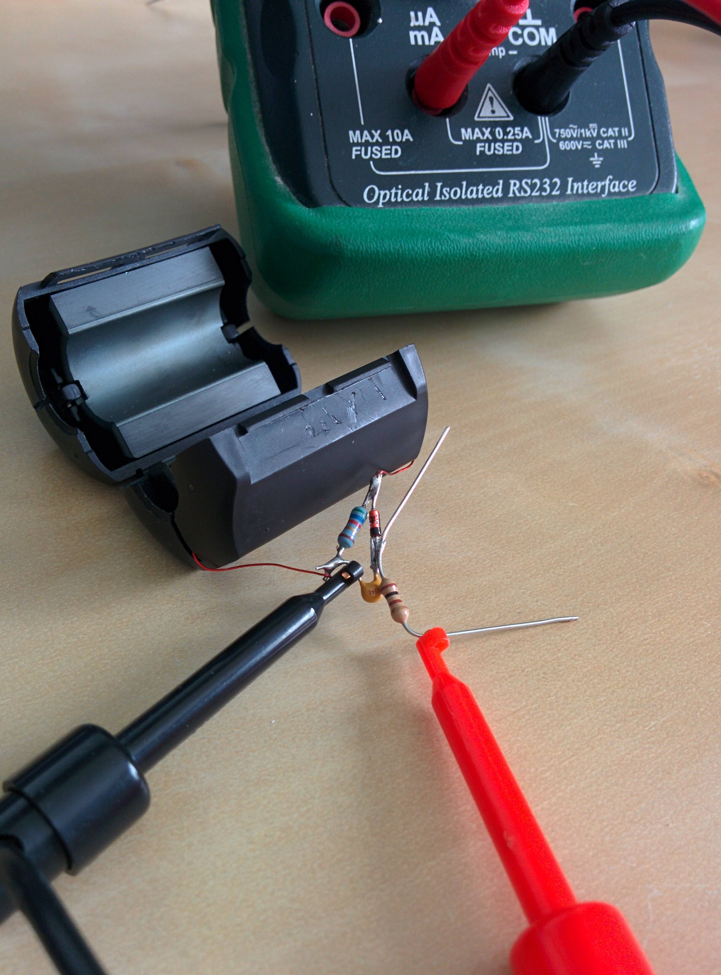
enter image description here

This device can be roughly calibrated by measuring the current through a known load. I put two half-watt, 100 ohm resistors in parallel, soldered them onto a connector, and plugged them into my transmitter as a 50 ohm dummy load. I set the transmitter power to minimum, clamped the ferrite around the resistors, and keyed up briefly. 5 watts into 50 ohms should give about 316 milliamps, and I read about 3 milliamps on the meter.

The non-linear diode will make the relationship between actual and measured current not linear, but that's good enough for a gross calibration.

other ideas

All kinds of devices can be used as detectors and probes.

An oscilloscope can work: try simply laying the probe next to the wire being measured, or making a loop probe. Put more turns in the loop for more sensitivity.
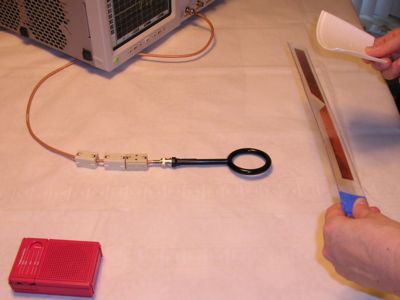
magnetic field probe orientation

A 2nd radio works also, without an antenna, or with a dummy load to reduce sensitivity.

making the measurements

Set up your probe. Transmit, and watch your detector. The strength of the signal it detects is proportional to the strength of the common-mode current. For long wires, take measurements at a few places: there may be standing waves with high impedance (low current) and low impedance (high current) nodes.

Considering reciprocity, if you can measure common-mode currents in a thing when you transmit, then that thing is also helping you to receive. Either isolate these things from the antenna, or make sure they are noise-free. Insufficiently isolated feedlines, and digital electronics injecting noise into home wiring are the biggest offenders.

$\endgroup$
3
  • 1
    $\begingroup$ @WarrenP Yes. The probes I describe here are crude probes that are easy to make. See Probing the Magnetic Field Probe for some detail on various designs. What you get for $3000 is a carefully calibrated probe, with a known and certified sensitivity and consistent performance. You'd need this for quantitative measurements of magnetic field strength, but for simpler qualitative measurements (do I have significant common-mode currents on my feedline or not? Have I made them better or worse?) a simpler device will do. $\endgroup$ Commented Feb 24, 2014 at 14:48
  • $\begingroup$ I suppose I don't need a calibrated value but knowing that they are "too low to be a worry" matters to me. $\endgroup$ Commented Feb 25, 2014 at 1:41
  • $\begingroup$ Late reply but hopefully youre still active on here. For the ferrite detector, when you say ten turns around the ferrite core, how exactly are you winding that? Is it around one side? Inside of it? $\endgroup$
    – Mark Deven
    Commented Jun 30, 2022 at 13:26
6
$\begingroup$

Another way to detect current on the outside of coax is to run your hand up and down the coax wile an analyzer is connected , if you see a fluctuation on the meter then current is following on the outside. On vhf I built sleeve chokes to remove it with great results. KC5ULU

$\endgroup$
3
  • 4
    $\begingroup$ Interesting...I've seen this effect, but didn't really understand the mechanism. Could you include an image or diagram of your sleeve choke? $\endgroup$
    – user14945
    Commented Jul 30, 2020 at 3:32
  • 3
    $\begingroup$ ..and welcome to Ham.SE! $\endgroup$
    – user14945
    Commented Jul 30, 2020 at 3:32
  • $\begingroup$ To 14945 The sleeve choke I made for 2 meters was simple . I used a piece of braded ground strap cut 1/4wave long . It can be opened up from the flat form to a tube slid it over a piece of rg8x coax , I cut small piece of outside covering off the coax 1/4wave down from antenna connection end to expose the copper braid then soldered the 2 bride's together. My coax was Tram rg 8x it has a nice bare copper to solder to but be fast and not melt the foam insulation between the center conductor on the coax cable. When measuring the 1/4 wave section be sure and be sure to allow for the velocity facto $\endgroup$ Commented May 23, 2021 at 20:35

You must log in to answer this question.

Not the answer you're looking for? Browse other questions tagged .