3
$\begingroup$

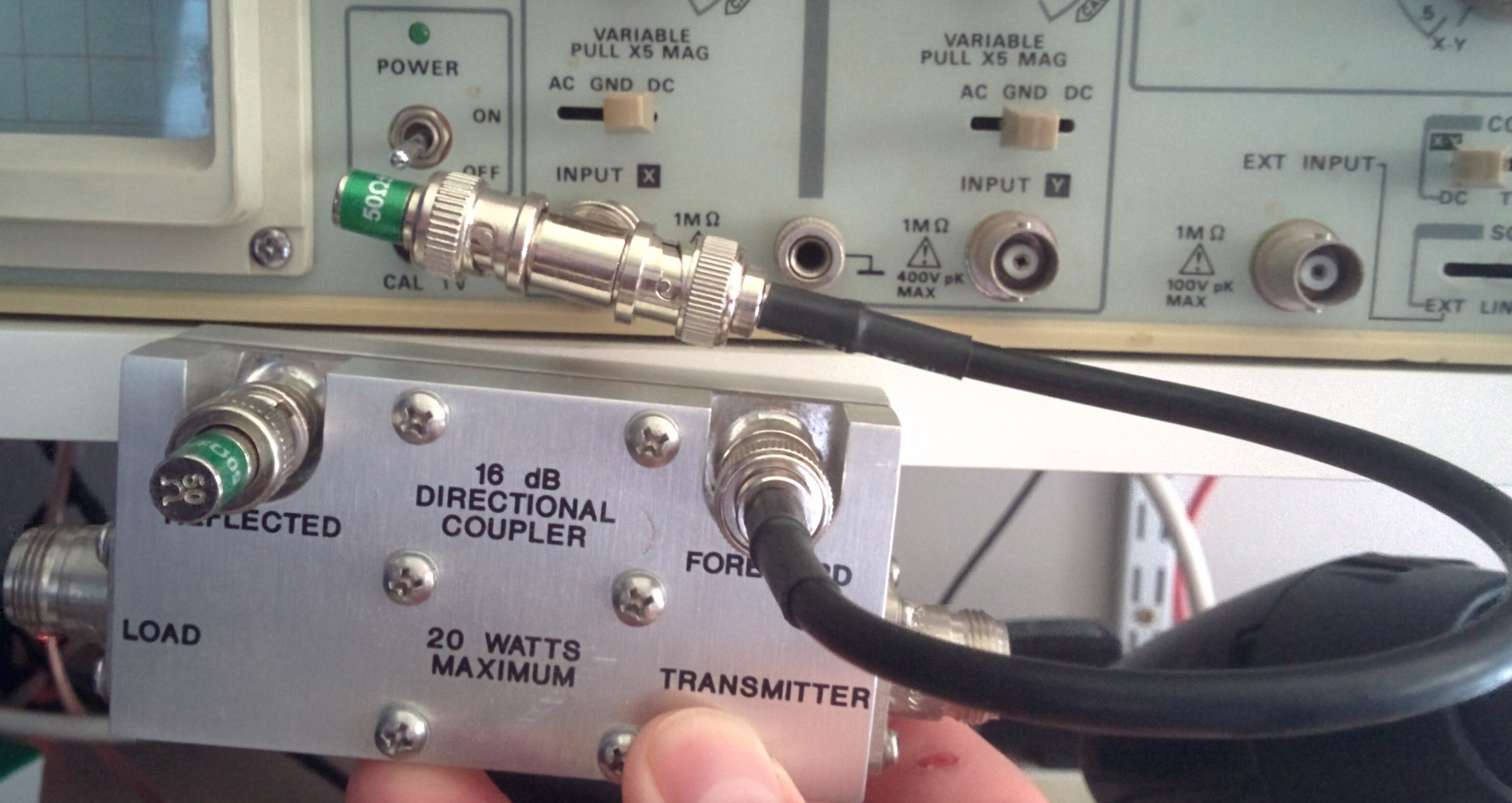
I've designed an pulsed RF generator (50-100 MHz) and am using a directional coupler to measure power into a 50 ohm dummy load. The forward power from the coupler is plugged into a o-scope (hi Z input). The issue is that I calculate what seems to be too much power (more than expected) that, while possible, I doubt.

My calculation is as follows: on scope I see 100 mV RMS, so this calculates as (0.1 V)(0.1 V)/(50 ohms) = 0.2 mW. Since the coupler constant is 60 dB, this means the mainline power is (0.2)(1e6) = 200 W. This seems high as the cw power during design was 100 W, although the 10% duty cycle certainly could enable 200 W during the pulses. Does this seem correct?

Also of note: the coupler (an older Werlatone, no longer manufactured) is rated for 5 kW. Could my measurements be caused by not reaching some threshold (using too little of coupler's range)? Also I checked the forward-power port resistance using a DVM and got 19 ohms, which I cannot make any sense of- expected short, open, or 50 ohms for this DC measurement. Any thoughts/comments appreciated!
$\endgroup$
7
  • 2
    $\begingroup$ You must match your scope's impedance to transmission line impedance. Otherwise, you will get wrong data! $\endgroup$ Commented Jun 9, 2017 at 18:41
  • $\begingroup$ i considered that after I left for the day (so will try). guessing this would halve my signal to 50 mV RMS, so this would be 50 W not 200 W.... much closer to expectations. but if coupler has internal 50 ohm termination (not known), wouldn't using 50 ohm scope impedance actually cause an error since port would now see two 50 ohms in parallel, or 25 ohms? $\endgroup$ Commented Jun 9, 2017 at 20:17
  • 1
    $\begingroup$ It's not a termination if something comes out... So, no a coupler doesn't have internal termination. A related device (a circulator with one terminated output) is the isolator, maybe you're referring to that? $\endgroup$ Commented Jun 9, 2017 at 21:21
  • $\begingroup$ The input Z of my scope is 20M/22pF. If yours has a high Z like this, you can put a BNC T-adapter on the scope input; put a 50 ohm terminator on one side, and the remaining side of the T is now your 50 ohm input. A terminator can be made by soldering a non-inductive resistor to (or inside) a BNC connector with minimum lead length. $\endgroup$ Commented Jun 9, 2017 at 23:03
  • $\begingroup$ You say a pulse generator and you are measuring 100 mV RMS. Have you done the math or is this really the peak or peak to peak value? $\endgroup$
    – Glenn W9IQ
    Commented Jun 10, 2017 at 14:56

2 Answers 2

3
$\begingroup$

A directional coupler only works if the coupled port or ports are terminated in the characteristic impedance, usually 50 ohms. Otherwise it's not able to accurately distinguish between forward and reflected power. This is apparent from the math governing its operation.

If your scope has a 50 ohm termination option, use that and run coax directly into the scope. Don't use a probe at all.

If your scope has no such feature, put a T and a 50 ohm terminator at the scope, like so:

enter image description here

This works well until you get into high UHF, where the physical size of the T becomes an appreciable fraction of wavelength.

Note my directional coupler is bidirectional, so I've taken care to terminate the unused reflected port as well.

Just be sure the power isn't too high to damage the scope. With a 60 dB coupling factor this is unlikely.

$\endgroup$
1
$\begingroup$

The -60 dB sampling port must be terminated with a 50 ohm resistor to match the impedance of the sampling device. You then connect your high impedance scope across this 50 ohm resistor to measure the voltage. Then simply apply Ohm's law to compute the power dissipated by the 50 ohm resistor on the sampling port. This will be 1/1,000,000 of your input power to the sampler or 1/999,999 of the power reaching the output port of the sampler.

$\endgroup$

You must log in to answer this question.

Not the answer you're looking for? Browse other questions tagged .