Well, I'm a little out of my depth, but this does seem to have all the usual parts of a gamma match: the matching section hanging off the main loop is a balanced transmission line, and the part connected to the BNC center is spaced off it, so the coax is coupled capacitively into that transmission line.
There are two transmission lines, and two gamma matches, one to the left and one to the right, I'm guessing one for each band. Getting a match on both bands will probably require adjustment in little steps with frequent checks on each band since the tuning for one band will have some effect on the other.
There's some information on how gamma matches work generally: What is a Gamma match in the context of the driven element of a Yagi antenna?
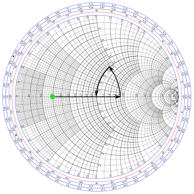
It appears the only adjustable thing here is the spacing of the capacitor. Most pictures of gamma matches use some arrangement with tubing to make a coaxial capacitor which slides for adjustment, but I don't see why this design wouldn't work the same way. Turning the screws to bring the pieces closer together increases the capacitance. That will move the feedpoint impedance along the path of the final arrow on this Smith chart: closer spacing -> higher capacitance -> longer arrow.

So, the idea would be if the feedpoint impedance is inductive, then turn the screws to bring the plates closer together. If it's capacitive, move them apart. You should be able to cancel out any reactance in the impedance. And if everything is right, you'll end up around 50Ω.
If all you have is an SWR meter, you are effectively measuring the distance from the center of that chart. In that case you don't have any information about which way you need to go, so you can just make small adjustments and see if it's getting better or worse. If the match is just terrible no matter what, it will be pretty hard to fix it except by trial and error. Might be a good excuse to build an impedance bridge :)