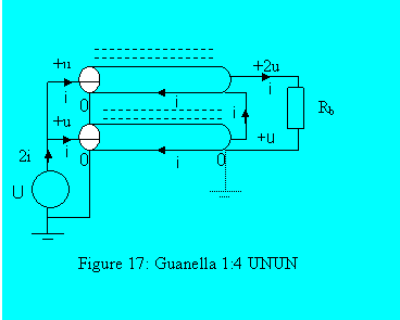
I am having trouble understanding the 1:4 Guanella current balun here. So at DC, or low frequencies, I think the current path would be a short to ground. At higher frequencies, I am getting confused on how the current path through the lower coax's inner conductor, whose return path is along the shield of the outer conductor, behaves. I get the concept that power is conserved, so if the voltage doubles, the resistance must quadruple (P=V^2/R). But, why does the voltage double? Does the extra current returning on the shield of the upper coax lower the ground potential? Or does it double the returning current on the shield while the inner conductors current is left unchanged?
-
1$\begingroup$ Is this from home.scarlet.be/on9cvd/… ? $\endgroup$– Phil Frost - W8IICommented Apr 20, 2021 at 13:20
-
$\begingroup$ Yes I did! You're explanation below, including your added link really clarifies it. The on question that confuses me still is the ground that is added on the right side of the lower coax. The confusion being that current would not flow from ground to ground, nor can there be a voltage drop across it. Thanks for the help on this! $\endgroup$– Erik McKeeCommented Apr 20, 2021 at 18:49
-
$\begingroup$ Yeah I'm not really sure what that 2nd ground is meant to indicate. Since it's drawn with dotted lines, I'd guess the author is somehow trying to indicate this is "not really" a ground, which is important because the potential there may not be (in practice, probably won't be) equal to the potential at the other ground. I'd just ignore it, really. $\endgroup$– Phil Frost - W8IICommented Apr 20, 2021 at 19:01
-
$\begingroup$ Fantastic explanation. These work extremely well, I can attest to that. $\endgroup$– Dan WheelerCommented May 14 at 12:55
2 Answers
It may help to consider that this:
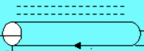
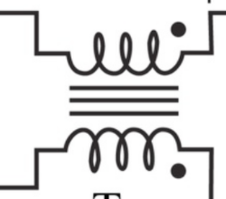
is equivalent to this:
The lines above the transmission line indicate it is wound on a ferrite. Because only the common mode affects the electromagnetic fields outside the coax, the ferrite increases the common mode impedance but does not affect the differential mode. To simplify analysis we can assume the common-mode impedance is infinite, and so the common-mode current must be zero.
The second diagram indicates two separate windings instead of coax. Because a differential current in the windings creates opposite magnetic fields that cancel, differential current doesn't "see" the core, and differential mode impedance is unchanged, whereas common mode current "sees" the core and a higher (assumed infinite) impedance. The mechanism is slightly different but the effect is the same.
Having accepted the equivalence of these two constructions, you should be able to follow other explanations of a Guanella balun.
-
$\begingroup$ Hi Phil, I have been thinking about the equivalency a lot. I agree differential current will not see the core in the lower picture. However, in the coax, you have current traveling down the inner conductor, and in the opposite direction on the inner wall of the shield conductor. The current that is added to the shield of the coax (from the signal pin of the lower coax) would travel on the outside braid of the shield conductor and not 'see' the inner conductor. The return current therefore should be 2i and there is not longer a differential current, its would be i going down, and 2i return? $\endgroup$ Commented Apr 28, 2021 at 16:38
-
$\begingroup$ @ErikMcKee It seems like you are assuming there will be some shield current in the upper coax besides what's drawn in the image, but there is not. The shield current isn't 2i, it's just i. The center conductor is also i but in the opposite direction. There is no common-mode current. There can't be a significant common-mode current, because the common-mode impedance is very high. $\endgroup$ Commented Apr 28, 2021 at 19:11
The voltage doubles because the two coaxial cables are connected in parallel on the input side, but in series on the right hand side.
In the diagram, there shouldn't be a little i in the middle of the upper coax, no common-mode current can flow there.
This trick doesn't work with batteries at DC, it just shorts out the supply, but at RF the choke, shown as the dotted lines on the upper coax, effectively disconnects it from the rest of the circuit. The coax through that choke, or wound around that core, is like a magic non-connected tunnel between left and right.
The twin-coax unun has very good high frequency performance because the two coax lines mean that the added voltages on the output are always in phase. The low frequency limit is where the choke no longer provides an impedance that is several times the output impedance, which depends on the ferrite, but within reason there is no impact on the high frequency performance by using a larger core and/or more turns. If the high frequency performance isn't important, say you only need 1.8 to 14 MHz, then the lower coax can be omitted entirely. This is also what you get from a 1:4 bifilar-wound unun on a single core.
-
$\begingroup$ Which little i are you talking about? The top and the bottom coax look identical, so if current can flow in one, why not the other? $\endgroup$ Commented Apr 20, 2021 at 16:46
-
$\begingroup$ The i in the middle of the upper coax, inside the choke. When the coax is drawn "closed" we have to assume this is common mode current, and there isn't any (top i = 0). The rest are all ok, including the common mode current on the lower coax (which is required of an unun) $\endgroup$– tomnexusCommented Apr 20, 2021 at 19:22
-
$\begingroup$ Ah! I hadn't considered to think of it like that at all. Could be worth expanding in the answer. $\endgroup$ Commented Apr 20, 2021 at 22:41


