According to Vincent D. Matarrese's Master's thesis, "Tapered radio frequency transmission lines" (Portland State University, 1992), there is a long history of using tapered-impedance transmission lines in matching systems. It's much too big a topic to review in an SE post, but the thesis is loaded with references for exploration.
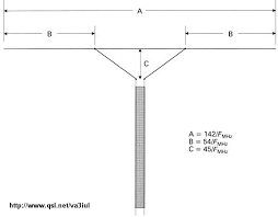
The Delta match is an example of the application of this technique:

It has been described in the ARRL Antenna Book for decades. PA3HBB gives equations that can be used to construct a delta match for a given matching situation.
We can begin to consider the prospects for your proposal by evaluating the impedance of bare-wire twinlead and fully-immersed twinlead. The impedance of a two-parallel-wire transmission line is:
$$Z_0=\frac{276\Omega}{\sqrt{\epsilon_r}}log_{10} \frac{D}{d}$$
valid for $(\frac{D}{d}>10)$, where $\epsilon_r$ is the relative permittivity of the dielectric material between the wires, $d$ is the wire diameter and $D$ is the spacing between them. For window line, the wires are not completely immersed in the dielectric material, so the lowering of the line's impedance is considerably reduced.
Using Polyethylene's $\epsilon_r$ of 2.5 as an example, the impedance of 18-ga conductors (d=0.0403-in) spaced 1-in apart would vary between $385\Omega$ for bare wires and $243\Omega$ if the wires were fully immersed in the dielectric. Even without "windows" in the dielectric, its effect is probably ameliorated by at least a factor of two, reducing the impedance variation to about $344\Omega$, which wouldn't provide very much impedance transforming capability.
As theorized by the OP, both the spacing and the quantity of dielectric material between the wires could be varied to increase the impedance range. Materials with higher $\epsilon_r$ would increase the impedance variation, but their cost-effective application to this problem seems challenging.
