A real antenna is more complicated, but I believe the insight you seek can be obtained by learning about a simpler case of transmission line stubs.
Consider what happens when a DC voltage is applied at one end of a transmission line, and it's unknown what's connected at the other end. It this is a 50 ohm line, that means for every 50 volts applied, 1 ampere of current will flow initially. That voltage wave propagates down the line until reaching the other end.
When the initial wave reaches the other end, if the line isn't terminated by a 50 ohm resistor, then the initial 50 volts per ampere is "wrong" for that termination. Say it's a 100 ohm resistor. Ohm's law dictates that for every 100 volts across this resistor, 1 ampere must flow through it. But when the wave arrives, we have 50 volts, and 1 ampere. How can this be resolved?
What happens is a new wave begins at the resistor, and propagates back towards the voltage source. Eventually this reflected wave reaches the voltage source, and it will "try" to increase the voltage. But a voltage source by definition always has a fixed voltage, so it will respond by reducing current.
This change then propagates back down the line towards the resistor. The superposition of all these waves that have happened now brings the conditions at that end closer to 100 volts per ampere, but we're still not there so another reflected wave is set up. The voltage source makes another adjustment to its output current, and these reflections continue on forever, each time approaching 100 volts per ampere. In practice they happen so fast that it's basically instant, and we just ignore this process of how voltage and current settle to equilibrium.
But when the voltage source is AC, and the transmission line is a significant fraction of the wavelength, now the time it takes to reach this equilibrium is no longer "instant" compared to how fast the voltage is changing, so we can't neglect it.
A special case is when the transmission line is a half wavelength long. In this case, the time it takes a wave to travel from the source, to the other end, and back is exactly 1 cycle. If we assume the source is a sine wave infinitely repeating, a delay of 1 cycle is identical to no delay at all. So if the transmission line is open at the end, that means voltage must be zero, and all that excess voltage is reflected back at the source. And because the line is a half wavelength long, that means the crest of that reflected wave arrives at the same time the source is at its crest. The two voltages add, creating a very high voltage for a very low current. That is, a high impedance. Ideally infinite, though in practice it will be limited by losses in the transmission line.
Another special case is when the transmission line is a quarter-wave long. In this case, the delay to make a round-trip is a half cycle, so the reflected waves arrive in the opposite phase. This has the effect of "inverting" the impedance: if the quarter-wave line is open at the end, it "looks" like a short to the source. It looks like a short because however much voltage the source tries to generate, it's never enough because the reflected wave cancels the source wave exactly. A very low voltage even for a very high current is the definition of a short.
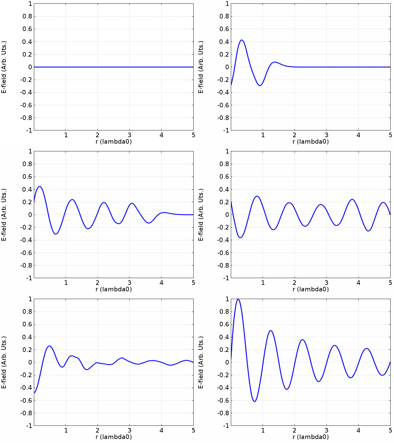
Here's an example:

By Davidjessop - Own work, CC BY-SA 4.0, Link
We can see a couple things going on here. Firstly, as the forward wave travels to the right, it's attenuated by loss. In an antenna, it could be attenuated by radiation.
Pay particular attention to the voltage at the ends. We can infer this particular example is terminated in a short, because the voltage at the right end is fixed at 0.
Initially, the source is able to develop some voltage into the line, looks like about ±0.5V at the peaks. But after the forward wave has reached the right, and then the reflected wave has reached back to the source, in the last moments of the animation, the voltage developed at the source is nearly zero. Were it not for the loss in the line, it would be exactly zero.
Finally note at 0.25 wavelengths on the horizontal axis, the peak voltage is almost ±1V, twice that of the initial wave from the source. This is because at this point, the forward and reverse waves are interfering constructively. That some points on the line have a very high RMS voltage, and other points have a very low RMS voltage indicates this line is operating with a high SWR. The SWR is exactly the ratio of RMS voltages between these nodes and antinodes.
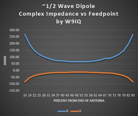
Antennas aren't exactly transmission lines, but the general principle still holds. The end of the antenna is like an open line: the current there must be zero because there's nowhere else to go. When center-feeding a half-wave dipole, each leg of the dipole is a quarter-wave long, so the high impedance ends of the antenna looks like a low impedance in the middle, a quarter wave away.
But if the leg(s) of the antenna are a half-wave, this impedance inversion doesn't occur. The source sees not a low impedance but a high one. Not infinite, since theoretically the antenna is still able to radiate. But such a high impedance does create issues in practice: it's hard to match if your transmitter expects a 50 ohm load.

