Back in ye olden days before SWR meters and auto-tuners, how was a ordinary household lightbulb used to help tune an antenna system? What did the circuit and tuning procedure look like?
-
2$\begingroup$ perhaps you've interchanged swr detector for dummy load ? $\endgroup$– glen_geekCommented Aug 23, 2018 at 12:25
-
$\begingroup$ Lightbulbs are known as notoriously bad dummy loads, because the impedance varies as the temperature changes, and the temperature changes with duty cycle. (Also, there's a fairly cool article about someone who did WAC on a 200w light bulb just to prove how silly it is.) I don't think lightbulbs were ever part of an intentional tuning procedure. $\endgroup$– user10489Commented Aug 24, 2018 at 1:35
-
$\begingroup$ The OQ asked "how was a ordinary household light bulb used to help tune an antenna system? What did the circuit and tuning procedure look like?". Therefore, I am moving your answer to a comment. $\endgroup$– Mike WatersCommented Aug 24, 2018 at 1:51
-
$\begingroup$ Ahh, I see now, very interesting. Shows what I know about history... I guess this explains the need for the dire warnings telling people not to do it in the ARRL literature. People were using lightbulbs, and they wanted to break that habit. $\endgroup$– user10489Commented Aug 24, 2018 at 11:21
2 Answers
I don't know much about this, but for what it's worth I do have a rather distant memory of doing this long ago, before transistor RF power amps became affordable and before I had a way to measure SWR or harmonic content of the transmitter output.
The transmitter was a very basic VFO, buffer and a 6V6 RF final, maybe 3 or 4W RF output max. The antenna was roughly 1/4 wave of wire strung out the window to a nearby tree (with an electric fence insulator at the end), using a pi coupler for matching, all very experimental and mostly built from parts of old valve receivers that I'd been lucky enough to be given. The valve output stage was robust enough to cope with severe mismatches. I remember getting RF burns from the antenna connection.
My equipment was only a small multimeter, a very simple field strength meter (that used the multimeter), a borrowed portable transistor receiver that had short wave bands, and a soldering iron, so there was a lot of guesswork and experimental method involved.
I was being mentored by a ham who was very kind and encouraging to me. He had lent me a copy of the ARRL handbook, and gave me ideas to try. He had been a Post Office/marine radio op in the war I think, and he knew a lot about getting things working with very little test equipment.
He told me that a (15W) 230V lightbulb in series with the antenna at the output of the pi coupler could be used as an indication of how much power was getting to the antenna. The pi coupler was adjusted until the lightbulb glowed brightest and it was then removed, and the field strength meter was used to peak the pi coupler settings.
Looking back on it I have little idea of how effective this method was in adjusting SWR, but I remember it made adjusting the coupler much easier than just using the field strength. The current in the bulb obviously does not actually indicate SWR, but serves as a rough initial indication of the matching of output stage to antenna I think. It was certainly quite reassuring to see direct evidence of current in the antenna circuit anyway.
Cheers.
-
$\begingroup$ The Pi-network output of those old tube transmitters could tune up onto many various types of loads, one being the light bulb. The main problem a new ham would have with this is thinking that tuning the transmitter into a light bulb removes the need to tune up into the antenna. A real antenna poses a different load (R+jX) to the lightbulb's (R+jX) load. Thus, tuning into a light bulb is not a substitute for tuning into your antenna. My transmitter at the time (early '60s) was an Eico 720, I used a light bulb for testing purposes only -- that is, does it work at all type testing. $\endgroup$– K7PEHCommented Aug 24, 2018 at 16:57
Mainstream hams first started to appreciate SWR in the 1940's. In that era some of the first SWR meters started to come on the market. But their accuracy and frequency range was quite limited. Toward the end of the 1940's military surplus coaxial cable was hitting the ham market. Up to that point, ladder line was typically used for most ham antenna installations.
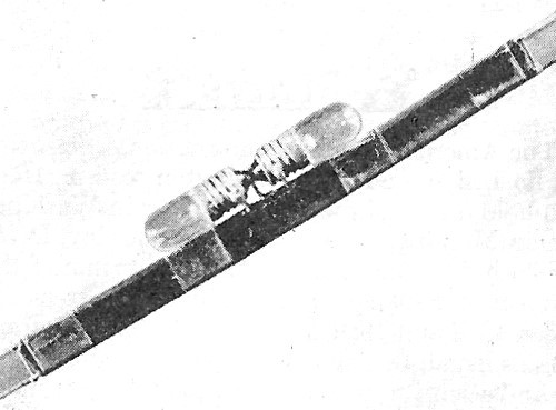
In October of 1947, Charles Wright, W4HVV wrote an article in QST bemoaning the accuracy and availabilty of SWR meters for "28 mc" and higher. His article, entitled The Poor Man's Standing-Wave Indicator, described a simple twin lamp (2 volt, 60 mA each) arrangement connected to a one turn pickup loop that when placed in parallel with the ladder line would give a relative indication of SWR.
When SWR is low, one lamp glows. As SWR increases, the second lamp begins to glow. By visually calibrating it using various dummy loads, the author was able to estimate the SWR.
Normally, the on-line QST archives are only available to members but I did find a full copy "in the clear" for your reading enjoyment here.
