Phase Relationship Between Source and Traveling Waves.
Imagine a transmission line with a pure sinusoidal non-reactive source at one end and a matched resistive load at the other. There will be a traveling wave of RF energy which is moving away from the source and down the line. There is no mismatch at the load, and so there are no standing waves anywhere along the line. The impedance everywhere on the line is a real number and is equal to its characteristic impedance .
Because the traveling wave is moving, the phase of it with respect to the source is a function of the position along the line as well as of time.
At 1/4 the wavelength of the frequency of the applied source along the line away from the source, the phase of the RF at that point with respect to the source is -90° or it lags the source by 90°. If you move to a point another 1/4 wavelength along the line the phase is now different, and is -180° with respect to the source.
Phase Relationship Between Source and Standing Wave.
If the load is removed from the above mentioned transmission line, now there is an open circuit at the end, and a standing wave appears along the transmission line. The standing wave is AC RF energy caused by the vector addition of the original or forward wave sent from the source and the wave reflected back from the open circuited end. The standing wave is now the only wave that can be seen on the line. This is just like when you mix yellow and magenta together and you get red, yellow and magenta are still there but all you can see is red. The original incident and the reflected traveling waves, while still present, are completely obscured by the addition of the each to the other. The phase of the original traveling wave sent from source can no longer be seen at all. Now the impedance everywhere along the line is determined completely and only by the standing wave and is a function of the distance from the open circuited end.
The standing wave doesn't move like a traveling wave, but is stationary and has a fixed amplitude profile along the length of the line. The standing wave is oscillating in amplitude everywhere at once along the transmission line at the frequency of the applied source, and its phase at any point with respect to the phase of the source is not a function of the position on the line, but is in fact the same everywhere.
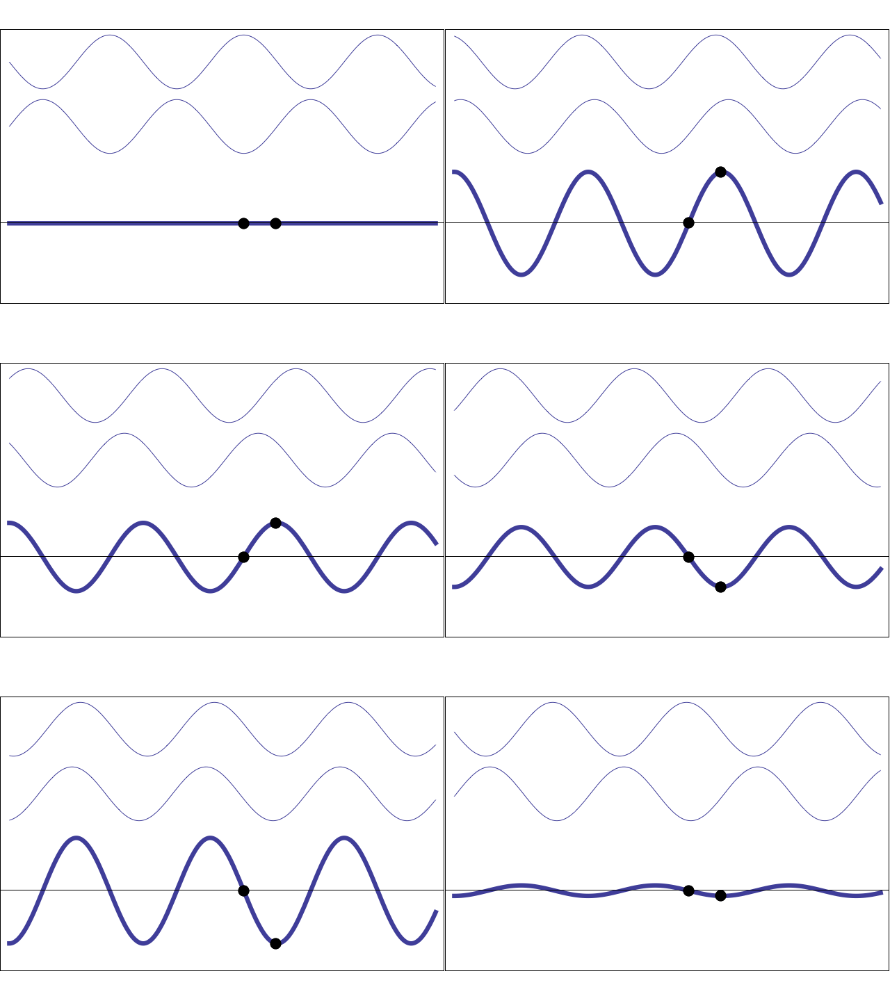
The animation below shows the phase relationship between the moving forward and reflected traveling waves at the top, and the standing wave at the bottom which is fixed in position.

If you think about it, it makes sense that the phase of the standing wave must be synchronized somehow to the phase of the voltage of the source, since the source is the thing that started the whole process off in the first place. It doesn't make sense for the standing wave to just have some arbitrary phase of its own.
When the source was first connected and the traveling wave was sent along the line toward the load for the first time, it took a specific amount of time for the wave to reach the load, and the time taken is directly related to how far it is from source to load.
When the wave reaches the load, then is when it starts to get reflected, and there is the relationship between the phase of the voltage of the source and the phase of the standing wave.
In actual fact, the phase of the voltage and current of the standing wave are changed when the standing wave is established at the open circuit end of the transmission line such that there is a difference of exactly 90° between each. At every point along the standing wave the voltage lags the current by 90°.
If the distance from the source to load is odd multiples of 1/4 wave length of the frequency of the source, then the standing wave current is in phase with the that of the voltage of the source, and the standing wave voltage is 90° out of phase with that of the voltage of the source.
Standing Waves on a Dipole Antenna.
It's common knowledge that the exact same situation just described for a transmission line exists in a dipole antenna. The dipole can be thought of as a spread out extension of the end of an open circuit transmission line, then the feed point becomes the source and the ends of the dipole elements behave in a similar way as the open circuited end of the transmission line. The main difference between a transmission line and a dipole antenna is that in the dipole the phase difference between voltage and current of the standing wave is a bit less than 90°, the departure away from 90° being the non reactive energy in the standing wave that is responsible for radiation.
Due to complete reflection at the open circuit ends, there is a standing wave on the dipole just like there is for the transmission line. The original traveling wave sent from the source and its reflection are obscured, and the phase of these traveling waves cannot be seen or measured, and the only waveform that exists on the antenna is a full standing wave.
At the ends of the elements, the magnitude of the voltage of the standing wave is always fixed at it's maximum AC value, and the current is always zero, so the difference in phase between voltage and is forced to be exactly 90°.
Furthermore, the phase of the standing wave everywhere on the antenna with respect to the phase of the source at the feed points is also fixed and constant and is determined by the distance between the feed points and the ends of the elements.
Awareness of these phase relationships is crucial in order to understand exactly what causes the reactance or lack there of present in the impedance of a dipole.
A Half Wave Dipole.
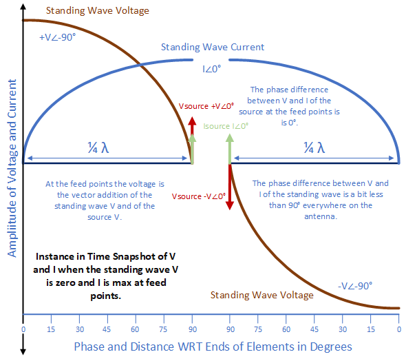
The diagram below shows a snapshot in time of the voltage and current of the standing wave along the length of a half wave dipole at the exact instant when the magnitude of the current of the standing wave is at a maximum.

For a half wave dipole, because the elements are exactly 1/4 λ in length and so the feed points are 1/4 λ away from the ends, the current magnitude maximum occurs exactly at the center of the dipole where the feed points are, and the voltage is always zero. As is the case with all dipoles of any length, the voltage of the standing wave lags the current by 90°, but because this is a half wave dipole with 1/4 λ elements, the phase of the standing wave voltage lags that of the source by 90° and the standing wave current is in phase with the source voltage.
Notice the vertical lines at both of the feed points. These represent the in-phase voltage and current of the source at the feed points. The voltage presented by the source adds vectorily to the voltage caused by the standing wave at the feed points.
This antenna has 4 reasons to be of interest to ham radio operators.
The phase of the current of the standing wave at the feed points compared to the phase of the source voltage is 0°. The quotient of source voltage and standing wave current at the feed points is a real number and so the impedance contains no reactance.
The phase of the voltage of the standing wave, which lags the phase of the current of the standing wave by 90°, compared to the phase of the source voltage, is -90°. The quotient of the voltage and current of the standing wave at the feed points contains the maximum reactance possible.
The standing wave voltage at the feed points which could contribute reactance to the impedance seen at the feed points if it wasn't zero all the time, is always zero all the time, and so does not contribute any reactance to the impedance seen at the feed points
The standing wave is reactive circulating energy in the antenna which is is being topped up exactly at the right moments by the source voltage, and so antenna current reaches a value which is much larger than the energy supplied by the source. Since radiation is proportional to the electromagnetic field intensity, and this field is proportional to the square of the RMS current in the conductors, the resonant antenna produces a much higher electric field intensity for a giving source current compared to when being operated at frequencies other than those which result in resonance. This is why everyone loves resonant antennas.
A Dipole Not Being Operated at Resonance.
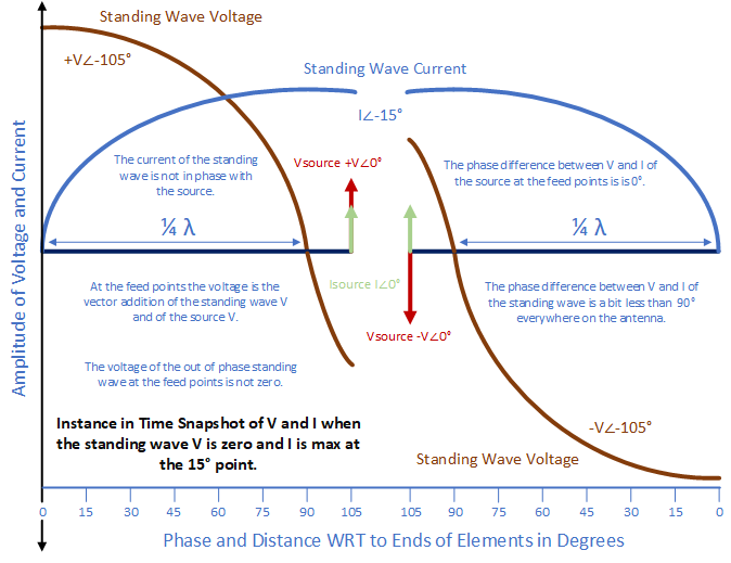
The diagram below also shows a snapshot in time of the voltage and current along the length of the standing wave on a dipole at the exact instant when the magnitude of the current of the standing wave is at a maximum, except this time it's for a dipole which has elements which are 15° longer than 1/4 or 90° of the wave length of the applied sine wave at the feed points. This means the entire antenna is 30° longer than the half wave length of the applied sine wave.

For this dipole, because the elements are not 1/4 λ in length and so the feed points are not 1/4 λ away from the element ends, the current magnitude maximum does not occur exactly at the center of the dipole where the feed points are, and the voltage is not always zero. As usual the voltage of the standing wave lags the current by 90°, but in this case the phase of the standing wave lags that of the source by 105° and the phase of the standing wave current lags the source voltage by 15°.
This antenna has 4 problems.
The phase of the current of the standing wave at the feed points compared to the phase of the source voltage is -15°. The quotient of source voltage and standing wave current at the feed points is not a real number and the impedance contains reactance.
The phase of the voltage of the standing wave, which lags the phase of the current of the standing wave by 90°, compared to the phase of the source voltage, is -105°. The quotient of the voltage and current of the standing wave at the feed points contains reactance.
The standing wave voltage at the feed points which contributes reactance to the impedance seen at the feed points isn't always zero.
The reactive circulating energy in the antenna isn't being topped up at the right moment and so antenna current isn't as high as it could be compared to when the antenna is operated at resonance. This is why some people don't like non-resonant antennas as much.
The Standing Wave Determines the Reactance in the Impedance at the Feed point.
At the feed points, whatever the voltage is of the standing wave adds vectorily to the voltage provided by the source.
For a dipole operated at resonance, the zero crossing point of the 90° out of phase voltage of the standing wave on the antenna falls exactly in the same position as the feed points, and so the magnitude of this out of phase voltage at the feed points is always zero and so contributes no reactance to the impedance seen at the feed points.
Because the current of the standing wave at all points on the antenna including at the feed points is in phase with the source, because the length of the elements are exactly 1/4 λ, it also doesn't add reactance to the impedance.
For a dipole not being operated at resonance, the out of phase standing wave voltage zero crossing point doesn't line up exactly with the feed points, and so at the feeds point there is a voltage which isn't always zero that is out of phase with the standing wave current and source voltage, and this adds reactance to the impedance. In addition, the current is also now not in phase with the voltage at the source and this too adds adds reactance to the impedance.
Because the original incident and reflected traveling waves which combined to form the standing wave are obscured by the addition of each to the other and so cannot be measured, the phase of these has no bearing on the impedance seen across the feed points, and the value of any reactance present in the impedance at the feed point is determined only by the phase of the standing wave compared to that of the source.
References
- The Similarity of Waves by John Shives https://www.youtube.com/watch?v=DovunOxlY1k
- Transmission Lines by Alexander Shure.
- Antennas by Alexander Shure.
- Practical Antenna Handbook by Joseph Carr Vol 4, Chapter 5 only.
- https://www.ittc.ku.edu/~jstiles/723/eecs 723 handouts.htm
- https://en.wikipedia.org/wiki/Dipole_antenna


