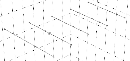
Definitely model the yagi elements as wires.
From the structure modelling guidelines: NEC2 segments should be no longer than about $0.1\lambda$ long (a bit longer is OK for straight wires with no junctions or corners). So a halfwave dipole or yagi element should be made of 5 segments, or 6 if you need a centre junction for some reason.

For the wire radius: they recommend segment Length/Radius to be greater than 8, so at 145 MHz the segment diameter can be up to $\lambda/40$ or 50 mm or 2". The extended thin-wire kernel (EK) allows thicker wires, with a segment length/diameter as much as 1:1, fully cube-shaped! BUT remember always that segments are an approximation of a wire and a thick segment is not a tube. Current can only flow down the length of the wire, not around it. Current is constant on the segment. So you can use thick segments to accurately model a 2m yagi made of 2" pipe, it will correctly calculate the self and mutual impedances, but you can't use thick segments to model a gamma match.
The segments getting too short and fat usually limits the number of segments. Also more segments are slower to simulate.
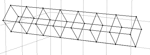
It wouldn't be possible or safe to model such a thin tube with a mesh. I would use solid segments up to about a 3" tube, and after that I'd consider approximating it with four wires, aiming for $\lambda/10$ or maybe $\lambda/20$ grid. Here is a cylinder 200 mm diameter, 1 m long, made with $\lambda/20$ segments:

Even if you have a metal boom, it's probably best to model the yagi with no boom. Then apply the boom correction to the elements before you build it. If the elements are mounted through the metal boom, then you need to make them longer by a small amount, the graph is as follows:

You could also experiment with adding a boom in NEC. Junctions with different segment diameters are a bit scary, so treat this with caution. If you add a metal boom and use an even number of segments for the wires, then you need to feed it with a pair of AFVS sources, one each side of the boom (with the voltage chosen to add not cancel of course).
The graph above is from the excellent book "Antennas in Practice" made freely available online by the authors.


