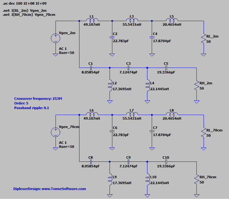
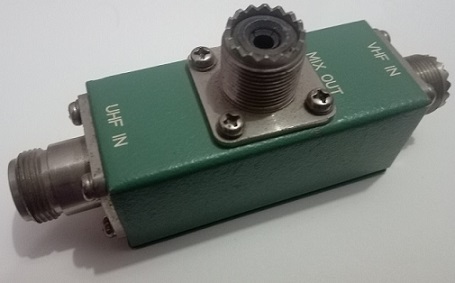
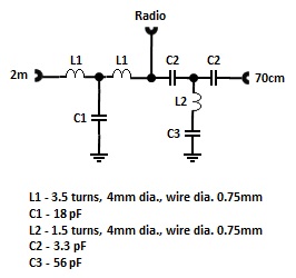
I'm trying to create a diplexer for the 2m and 70cm bands so that two antennas can share a feedline to my "shack". My radio is a Yaesu FT60 handheld, 5W max.
I have home made a j-pole for 2m, and a neat little ground plane antenna for 70cm, both of which show an SWR under 1.2:1 throughout their respective band, according to my Rig Expert. Both antennas have been analysed under various different feedline and mounting arrangements, with SWR curves staying very consistent - pretty confident about these results.
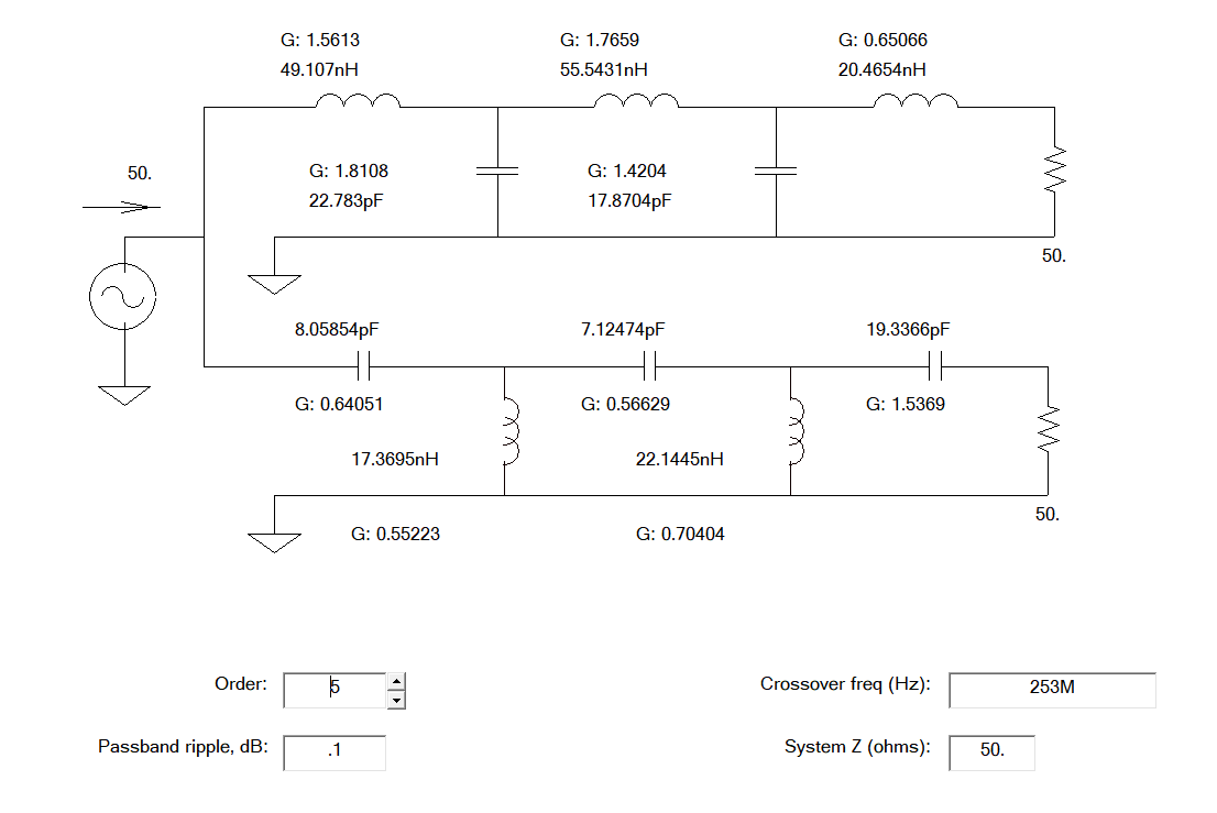
So I found this circuit on the internet:
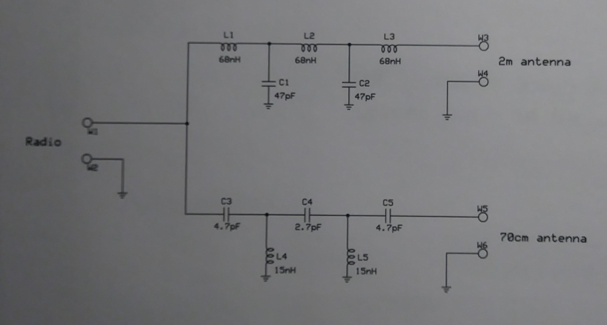
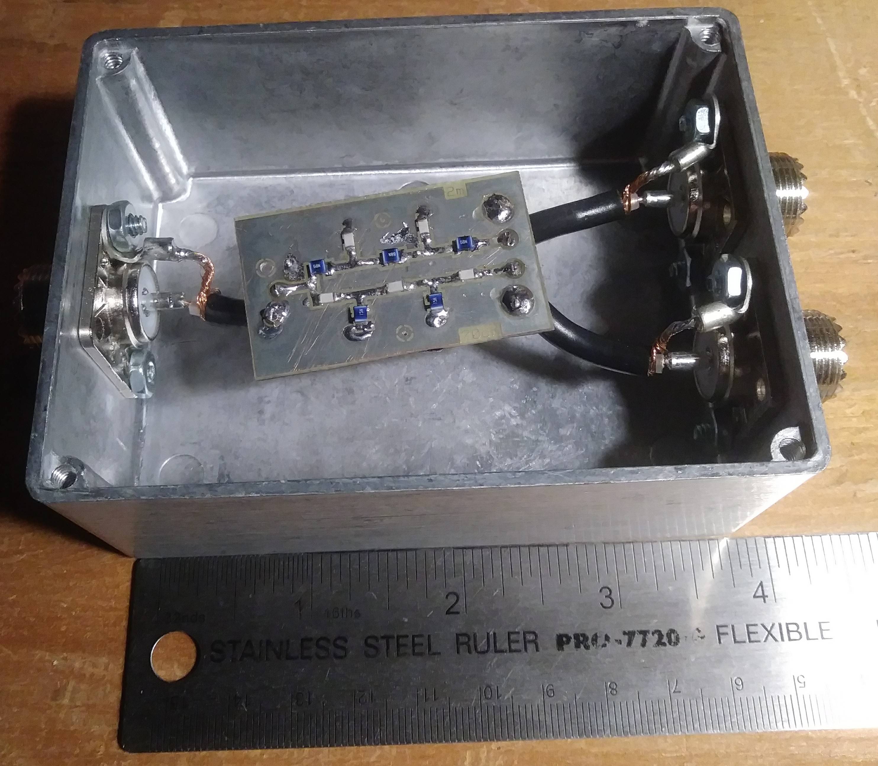
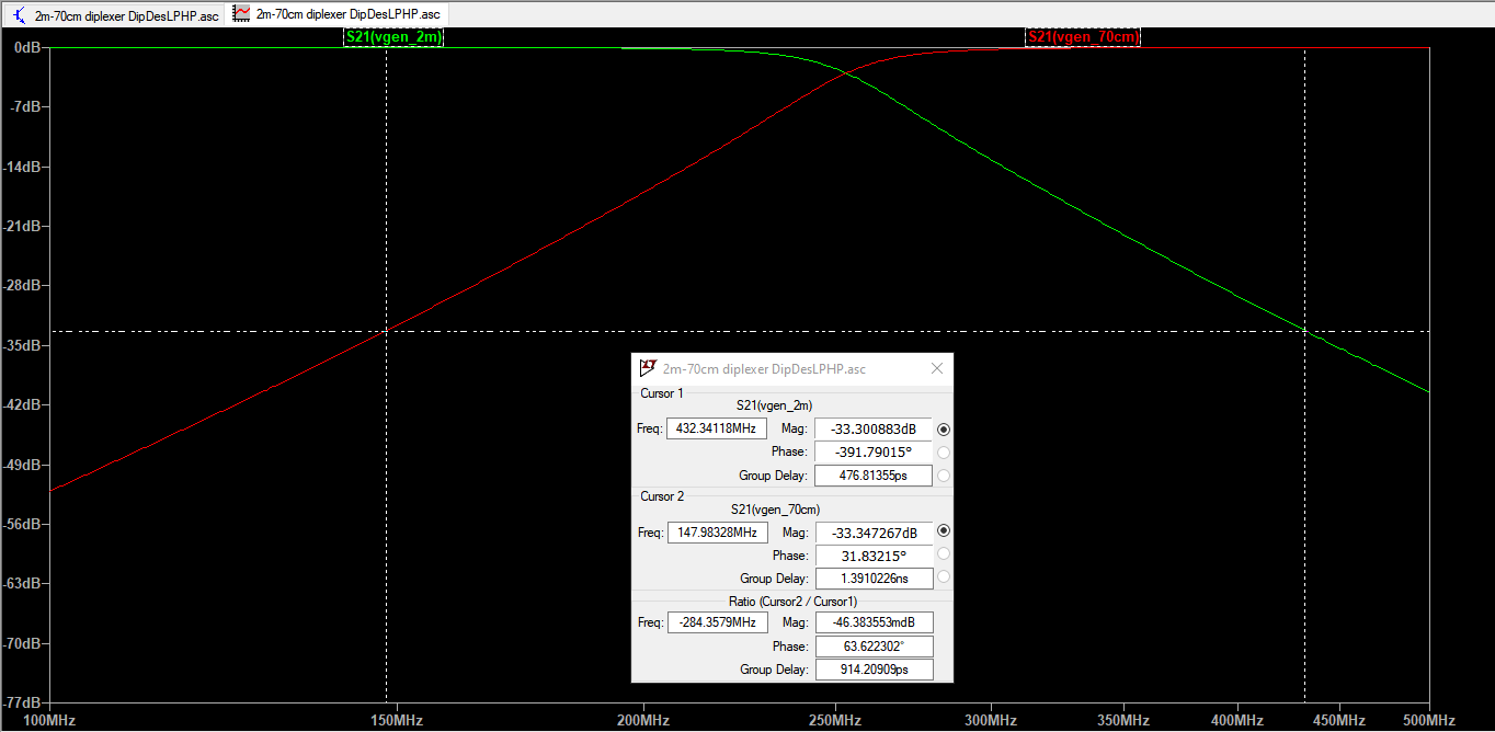
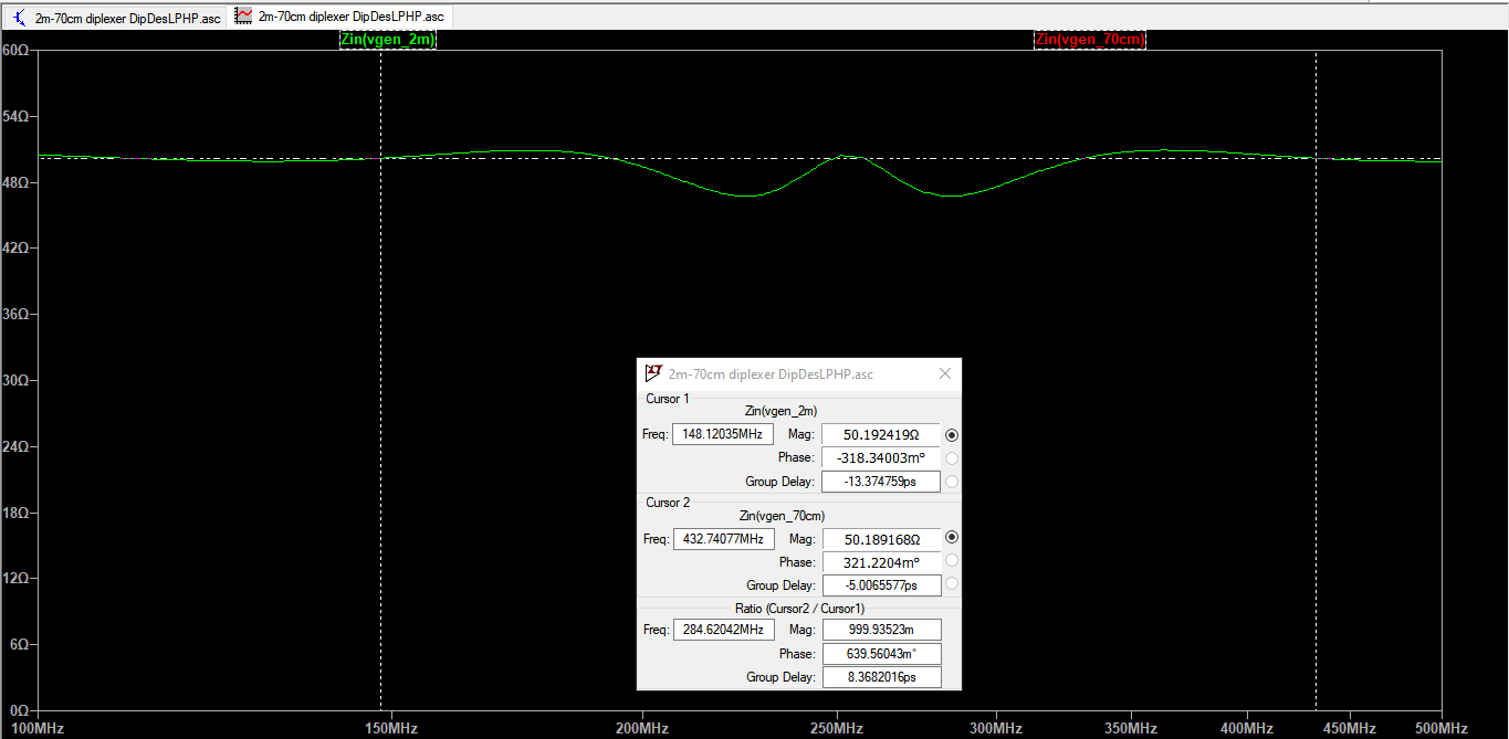
I simulated it in LTspice out of curiousity and the response looked legit, so I whipped up a little single-sided PCB and soldered the components on. (without my magnifiers and with a very wonky tip, sorry)
I put this PCB in a stylish aluminium alloy box, with short stubs of RG58 connecting the I/O solder pads on the board with SO-239s mounted to the box.
Unfortunately, with the diplexer installed on my main feedline (~25 feet of LMR-240) and each antenna connected to its respective SO-239 with about 3 feet of RG58, I'm looking at between 3:1 and 4:1 across both bands.
I have carefully examined and electrically tested the PCB and the RG58 stubs/connectors for dead shorts or other issues but can find none.
Is there something obviously "wrong" about what I've done here?
(not sure what tags are most appropriate for this question, suggestions welcome)
Cheers!!
