2
$\begingroup$

I previously posted this in electronics StackExchange here, but I believe Ham is more proper place for it as it closely relates to antennas.

I'm curious if it is possible to build a spark-gap Tesla coil without using capacitors on the primary side at all? Basically, treating primary and secondary as TX/RX antennas and cutting them to proper length so that the primary is producing a certain frequency and secondary is tuned to it by using a wire length that is integer multiple of the length used in primary. Then using a HV source and spark gap to excite the primary at its natural frequency (half or quarter-wave, whatever it happens to be). Do you think it is possible to create SGTC this way so that it is into tens of MHz range? Do you see any pitfalls here?

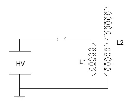
Here's a crude drawing of this.

Here's a crude drawing of it

Let's assume L1 and L2 are quarter-wave helical antennas, L2 being a smaller diameter one surrounded by L1. In order to tune the L2 to the frequency that L1 produces, you would normally need them to be the same length, but in this case we can't create a voltage step up configuration (we would need more turns in the secondary). But since L2 is also resonant at odd multiples of the quarter wavelength, like 3/4, 5/4, 7/4 etc, by having the wire length that is N times larger than that of a primary (where N is an odd number), the secondary should also be resonant on the same frequency while still providing means for stepping the voltage up.

Just to give you an idea, here's a video of my B&W 3034 antenna coil in spark-gap Tesla coil configuration (quarter-wave) using resonant caps. What I'm trying to do is remove these caps and tune this as if the two coils were antennas. The length of this B&W coil is around 19 meters so if I manage to tune it to 5/4 wavelength, the primary will have to be 3.8 meters long which seems to be doable.
$\endgroup$
9
  • $\begingroup$ I think you should show a schematic of what you mean. $\endgroup$
    – user21417
    Commented Feb 10, 2022 at 13:28
  • $\begingroup$ @jdv I've modified the question to include some crude drawing along with some more info $\endgroup$
    – elgroovy
    Commented Feb 10, 2022 at 15:18
  • $\begingroup$ Please edit your question to include the important information from the text in the picture. Text in the picture can't be read by deaf people using screen reading software; neither can it be found by search engines, or translated by online translation tools for people whose primary language isn't English that want to follow the discussion. $\endgroup$
    – rclocher3
    Commented Feb 10, 2022 at 15:41
  • $\begingroup$ Thanks for disclosing the cross-post, but please don't do that again. Pick one site or the other. To those who question the relevance of this question on this site, I believe the question is relevant here because of the strong similarity of the described device to early spark-gap transmitters. $\endgroup$
    – rclocher3
    Commented Feb 10, 2022 at 15:52
  • $\begingroup$ I just added a video demonstration of a coil in operation and some more info to the original question. @rclocher3 will do those now as extra edits, thanks $\endgroup$
    – elgroovy
    Commented Feb 10, 2022 at 16:00

1 Answer 1

3
$\begingroup$

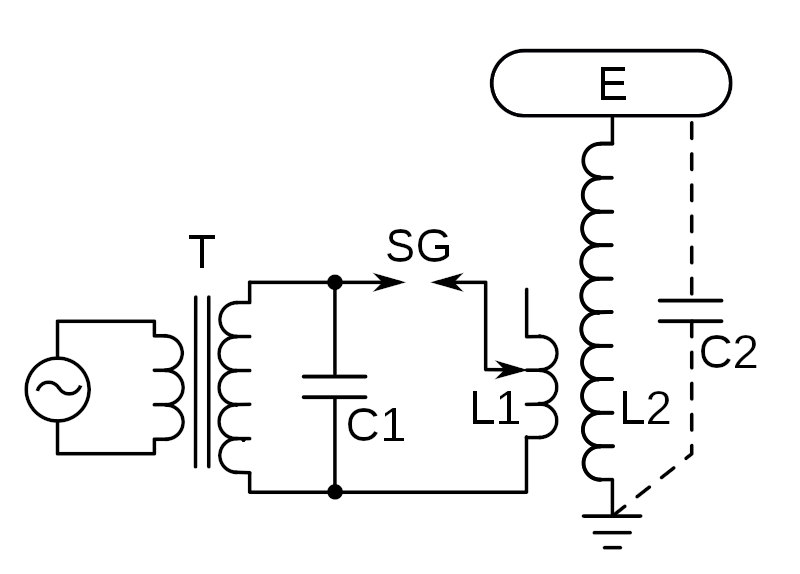
Here's a schematic of a spark-gap Tesla coil from the Wikipedia article:

schematic of a spark-gap Tesla coil

L1 and L2 are coupled together by their magnetic fields, and so act as a transformer. Such a Tesla coil depends upon resonance to create the oscillations that allow the L1-L2 transformer to work. The parasitic capacitance C2 helps (but wouldn't be able to start oscillations on the L1 side by itself).

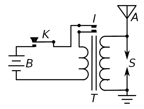
Here's a schematic of a Marconi monopole spark-gap transmitter from before 1897, from the Wikipedia article on spark-gap transmitters. The component labeled "I" is an interrupter, a mechanical device that turns the DC from the battery into AC that the transformer can use, similar in spirit to the circuit that rings an old-style alarm bell. (Hat tip to @hobbs-KC2G.)

schematic of a pre-1897 Marconi monopole spark-gap transmitter

This transmitter worked, but it wasn't very efficient. The Wikipedia article lists several disadvantages:

The primitive transmitters prior to 1897 had no resonant circuits (also called LC circuits, tank circuits, or tuned circuits), the spark gap was in the antenna, which functioned as the resonator to determine the frequency of the radio waves. These were called "unsyntonized" or "plain antenna" transmitters.

The average power output of these transmitters was low, because due to its low capacitance and inductance the antenna was a highly damped oscillator (in modern terminology, it had very low Q factor). During each spark the energy stored in the antenna was quickly radiated away as radio waves, so the oscillations decayed to zero quickly.

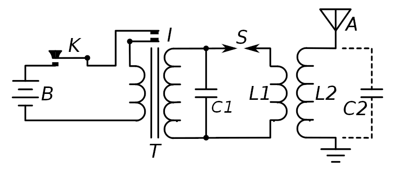
Around 1897 several researchers came up with a greatly-improved transmitter:

schematic of a post-1897 spark-gap transmitter that includes a capacitor

Quoting from the Wikipedia article again:

The primary winding of the oscillation transformer (L1) with the capacitor (C1) and spark gap (S) formed a "closed" resonant circuit, while the secondary winding (L2) was connected to the wire antenna (A) and ground, forming an "open" resonant circuit with the capacitance of the antenna (C2). Both circuits were tuned to the same resonant frequency. The advantage of the inductively coupled circuit was that the "loosely coupled" transformer transferred the oscillating energy of the tank circuit to the radiating antenna circuit gradually, creating long "ringing" waves. A second advantage was that it allowed a large primary capacitance (C1) to be used which could store a lot of energy, increasing the power output enormously.

You might be able to make a spark-gap Tesla coil without a capacitor that uses coupled antennas instead, but I'd suspect that it wouldn't work very well if it worked at all, for the same reasons that pre-1897 spark-gap transmitters without capacitors didn't work well.

But I'm just a person on the internet with an opinion who hasn't built either a Tesla coil or a spark-gap transmitter, so please don't let me stop you from trying. I'd be happy to be proved wrong!

I should mention that spark-gap transmitters have been illegal in most countries since a treaty was passed in 1934, because they are very broad-banded and noisy, and have enormous interference potential. Tesla coils surely radiate lots of noise also, but they're legal because they don't include antennas. If you make a Tesla coil that includes any kind of antenna-like component, please shield it so that it doesn't illegally radiate strong noise across tens or hundreds of megahertz. Perhaps you could put the whole thing inside a shipping container.

$\endgroup$
2
  • 2
    $\begingroup$ I is an "interrupter", it's a mechanical device that turns the DC from the battery into AC that the transformer can use. Similar in spirit to the circuit that rings an old-style alarm bell — a spring-loaded contact closes the circuit, which energizes a coil, which magnetically pulls the contact back open, so it oscillates (or something like that, there were many variations on interrupters over the years). $\endgroup$ Commented Feb 10, 2022 at 18:23
  • $\begingroup$ Thanks for your input. "I" on the diagrams seems be to an interrupter tied to T which is an Induction (Ruhmkorff) coil that was quite popular back in the spark-gap radio era. Since pre-1897 spark-gap transmitter is basically a HV source directly connected to the antenna, It happens to be only a transmitting part and the receiving end (like in Hertz's apparatus from 1887) is missing. $\endgroup$
    – elgroovy
    Commented Feb 10, 2022 at 18:26

You must log in to answer this question.

Not the answer you're looking for? Browse other questions tagged .