4
$\begingroup$

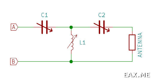
I would like to build a 100W T-network antenna tuner:

enter image description here

I have a 12-pole wafer switch, 12.5 meters of enameled copper wire (d=1.5mm) and a pair of 12-365pF variable capacitors rated 200V DC (dielectric strength) 250MΩ (insulation resistance).

There are some doubts regarding the capacitors. They are quite small (about 3x3x3 cm) and the plates are placed very close to each other. I have MFJ-971 tuner and it uses much larger capacitors which have much more space between the plates. Although this tuner is rated 200W.

I believe there are three problems. The first one is that the capacitors voltage rate is provided only for DC, but I'm going to apply AC. I don't know whether it's possible to convert DC rate to AC rate. The second problem is that I don't know how to estimate the maximum AC voltage that will be applied to the capacitors in the T-network. Finally, I could just build a tuner and check whether the capacitors will arc, but I don't know how to do it without the risk of damaging the transceiver (Yaesu FT-891).

Basically my question is: how to determine (theoretically, experimentally or both) whether it's safe to use given capacitors in this network?
$\endgroup$
3
  • $\begingroup$ Need to know the impedance you will match to determine the voltage across the capacitors. Or, tell us about the antenna so we can estimate the impedance. $\endgroup$
    – Brian K1LI
    Commented Apr 5, 2019 at 10:53
  • $\begingroup$ At the moment I have two antennas that require a tuner. The first one is a long wire antenna (23.5 meters + 8 meters counterpoise). The length was chosen so that the impedance should be relatively low on any band from 80 to 10m. The second one is a multiband (40-10m) inverted delta loop, 38 meters total length, the feed point is in one of the upper angles. It supposed to be about 120 Ohm on 40m, although I'm not certain about other bands. Also I would like to use a tuner for a multiband 7-10m long vertical antenna (fishing rod + tripod + wire + radials), although currently I don't have one. $\endgroup$ Commented Apr 5, 2019 at 11:22
  • $\begingroup$ The T-network's operating (loaded) Q varies hugely depending on the load impedance. And the voltage across the capacitance can be quite large when the load impedance is high. There is no direct way to figure out the max voltage. A typical way to do that is to define the maximum SWR the tuner should be able to match, and on that constant SWR circle, find the worst point and then calculate the voltage across the capacitor. $\endgroup$ Commented Oct 26 at 22:58

1 Answer 1

4
$\begingroup$

I made a NEC model of an antenna with the dimensions of your "long wire" on 14.2MHz, found the values of C1, L1 and C2 that produce a 50$\Omega$ match and simulated the network to observe the voltages across the capacitors with 100W dissipated in the load. The voltage across C1 was 220VRMS, over 300V peak. Given all the variables that I did not evaluate, plus good design practice to allow considerable margin, I would say that your capacitors will not support 100W transmissions.

Qualitatively, this result agrees with the 500VRMS, minimum, recommended in the 100W Z-match in the ARRL Handbook.

$\endgroup$

You must log in to answer this question.

Not the answer you're looking for? Browse other questions tagged .