0
$\begingroup$

I have two antennas in my station: a 10-15-20M yagi, and a loaded 40M vertical.

With the ATU built into my Kenwood TS-450S I can operate 80, 60 a and 30M with the 40M vertical too. Though, in 80M I have had very little luck being heard except for local stations.

Would it make a significant difference if I used an ATU at the base of my vertical, instead of tuning it with the built-in tuner?

I'm aware of the feedline losses due to mismatching, but I'm not sure how this translates to real world ability to transmit.

I'm an electronics hobbyist and I've been thinking of building a remote ATU: switchable inductors of 8-4-2-1-0.5uH (which should be able to make any combination of 0 to 15.5uH in 0.5uH steps), and a similar arrangement for capacitance, to build a L-network that should be able to tune the monopole to basically any frequency in the 80, 60, 40 and 30M bands. But I'm wondering if going through all this hassle would give me any significant advantage over just using my built-in ATU.
$\endgroup$

2 Answers 2

2
$\begingroup$

Even if the mismatch losses are relatively low, since your loaded 40-m vertical is electrically short on that band, it's really short on 80-m and your expectations need to scale down in a similar ratio.

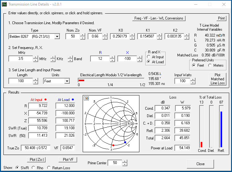
The amount of mismatch loss you experience depends on the degree of mismatch between the load and the feedline, as well as the feedline's matched loss. You can calculate the loss using AC6LA's free TLDetails calculator:

enter image description here

To get accurate results, it's important to know the impedance on 80m looking into either the feedline or the feedpoint of your 40m vertical.

If you decide the loss is excessive and you are running 100-W or less, you might want to construct a kit based on the ATU-100 developed by N7DDC. As of this writing, full kits are available on eBay for about US$35.

$\endgroup$
5
  • $\begingroup$ At one point i measured the feedpoint impedance of my antenna and it was 8-245j at 3.5mhz $\endgroup$
    – hjf
    Commented May 29, 2020 at 23:12
  • $\begingroup$ What do you get when you plop that into TLDetails with your feedline type and length? $\endgroup$
    – Brian K1LI
    Commented May 29, 2020 at 23:14
  • $\begingroup$ Tells me 95% of the power is lost in the feedline heh. What I don't understand is, where does the "mismatched power" go when using a match at the feedpoint? $\endgroup$
    – hjf
    Commented May 29, 2020 at 23:16
  • $\begingroup$ No, I mean when the matching network is at the feedpoint of the antenna. Is it dissipated by the matching network? $\endgroup$
    – hjf
    Commented May 30, 2020 at 3:33
  • $\begingroup$ @hjf Apologies; see my detailed answer. $\endgroup$
    – Brian K1LI
    Commented May 30, 2020 at 9:38
1
$\begingroup$

In a comment, the OP asks an interesting and important question: "...where does the 'mismatched power' go when using a match at the feedpoint? Is it dissipated by the matching network?" AE6TY's SimSmith, another excellent and free tool, lets us get the answer.

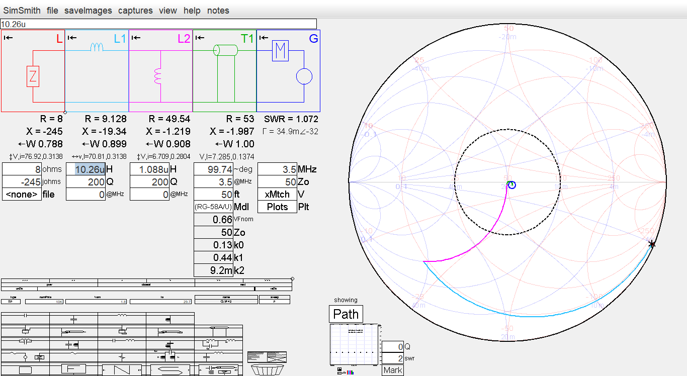
For demonstration purposes, I assumed your feedline is 50-ft of RG58-A/U and that inductors of Q=200 could be used. (Note: from experience, I know that this is easily achieved, even using powdered-iron toroid cores.) Working from the 8-j245 $\Omega$ at 3.5-MHz provided in the OP's comment, SimSmith shows that a simple L-network of inductors will match the antenna to 50-$\Omega$ cable:

enter image description here

Of the 1.0-W applied to the transmission line, 908-mW makes it to L2 and 788-mW makes it to the load. Those ratios represent about 1-dB of total loss in the L-network and TL, of which 0.4-dB are lost in the TL.

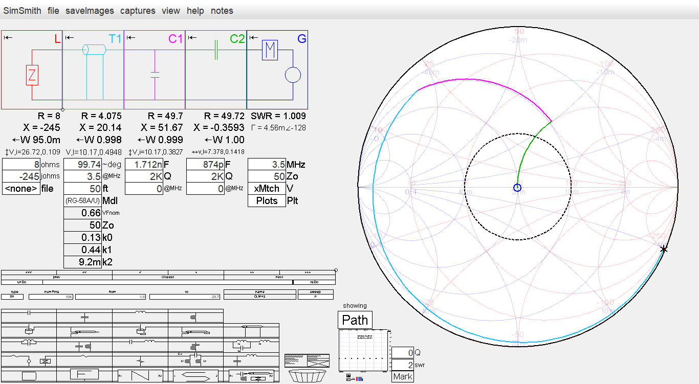
For comparison purposes, let's examine what would happen if the match was effected at the rig end of the TL:

enter image description here

Only 95-mW of the 1-W applied to the matching network makes it to the load, a loss of 10-dB, nearly all of which is dissipated in the TL!

So, the answer is that using quality components in a properly designed matching network placed at the load, the power delivered to the antenna for radiation can be increased by about 9-dB rather than being dissipated in the transmission line.

$\endgroup$
2
  • $\begingroup$ Excellent, so most of the power goes into the antenna anyways. you made a remark there about iron powder inductors. What if I were to use air cored inductors instead? M0UKD's calculator says my air cored inductors should have Q higher than 200 at the frequencies of interest. The Yaesu FC 40 seems to use air cored inductors as well. $\endgroup$
    – hjf
    Commented May 30, 2020 at 13:42
  • 2
    $\begingroup$ Well-designed air-core inductors will deliver high-Q, as long as they aren't close to objects that will introduce loss. I mentioned powdered-iron toroid cores because there seems to be a perception in some quarters that their Q isn't adequate. You may find that toroidal inductors are more amenable to compact enclosures. $\endgroup$
    – Brian K1LI
    Commented May 30, 2020 at 14:44

You must log in to answer this question.

Not the answer you're looking for? Browse other questions tagged .