There's a lot of information available about how to block common mode current originating at the antenna end of a coax cable. But, I haven't seen any reference to common mode current originating at the transmitter. If common mode current is on the outside of the cable's shield (as many people describe it), and both the inside and outside of the cable braid are connected to the same wire in the radio (which they are), and the feed line is the right length to be an effective radiator (which could happen), wouldn't the shielding be radiating like crazy? That doesn't seem to happen in real life, so I feel like I'm missing a crucial piece of information here. What's stopping common mode current from originating at the transmitter?
4 Answers
The short answer is that it can't.
A shielded transmitter, connected to an ideal piece of coax, does not generate common mode currents.
The inner and the outer of the cable look connected (and for Direct Current they are), but high frequency currents really cannot pass through the thick metal, they are confined to the inside or the outside.
Real coax can leak, but in practice it's very little.
Here are some examples.
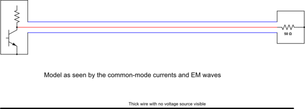
First - a simple coaxial cable connecting a transmitter to a dummy load. See how the Inside and the Outside of the coax never meet - they really are separate worlds. No RF current can reach the outside of the coax. There are no common-mode currents.

simulate this circuit – Schematic created using CircuitLab
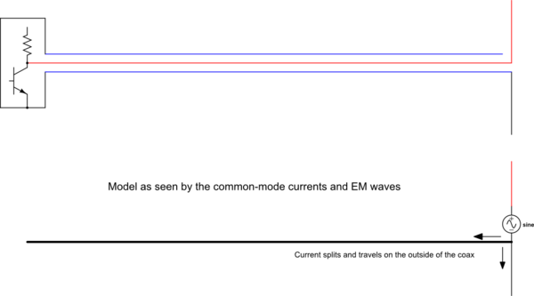
Second, a shielded transmitter feeding a length of coax, connected to a balanced antenna without a balun, which creates the unbalanced currents.

Balanced lines
I should mention that it is not only coax that can be used to generate balanced currents, it's just the example you asked about.
If the transmitter drives a balanced line with equal and opposite voltages, say with a transformer, there will be no unbalanced voltage, and no common-mode current. Ethernet cables are like this (CAT5 etc, before they were shielded). There is very little radiation from the pair, even though it is carrying significant RF power, because the transformer that feeds it has a high common-mode impedance, and the other end is an identical circuit, not an antenna.
Generating common-mode currents on purpose
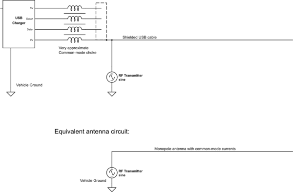
It is possible to generate common mode currents at the transmitter, but generally we take pains to avoid doing that. Here is an example where it is desirable - I have a bluetooth-receiver-FM-transmitter gadget in my car, which works best if there's a USB cable plugged in. It uses the USB cable in common mode as the antenna. Separately, inside the shielding, the USB D+ and D-, and 5V and 0V, are available as differential signals to the phone. The same is done in phones that have FM radio receivers, using the headphone cords.

-
$\begingroup$ The diagrams help. It looks like you can avoid common mode current from the transmitter if the transmitter is in a shielded enclosure. That makes sense. What if it's an a plastic box? Would there be any way to avoid common mode current in that case? I'm guessing it would depend on the RF wavelength and the lengths of the exposed wires, right? $\endgroup$– mrogCommented Mar 10, 2020 at 17:04
-
$\begingroup$ @mrog yes exactly. If the radio isn't completely sealed, then it will radiate. But as you say, it depends on the wire lengths. HF radios may have exposed transistors and coils. GHz radios will have it all shielded in cans, mainly to prevent signals from leaking in on receive. $\endgroup$– tomnexusCommented Mar 10, 2020 at 18:23
-
$\begingroup$ This analysis ignores the fact that the outer shield of the feedline is a certain length of conductive wire in the antenna's EM near field. Thus having the same problem as gutters, etc. that are too close to an antenna. An antenna radiates nearfield EM. Thus different from a dummy load. $\endgroup$– hotpaw2Commented Mar 14, 2020 at 22:57
-
$\begingroup$ Shielding a transmitter won't prevent common mode radiation. If there's "RF in the shack", the transmitter shielding (and its length of ground wire) becomes an antenna. A field strength meter will detect. $\endgroup$– hotpaw2Commented Mar 14, 2020 at 23:03
I haven't seen any reference to common mode current originating at the transmitter.
Likely, you won't. As Tom pointed out, transceivers use unbalanced to unbalanced connections (where the coax plugs into the rig).
It could be argued that the common-mode currents on the outside of the shield do originate at the transmitter, but it is unbalanced to balanced connections at the antenna which can cause the RF from the transmitter to appear on the outside of the shield.
The outside shield of a coax can “radiate like crazy”, depending on the antenna and feedline configuration. This effect is sometimes noticed when shifting a feedline noticeably changes the SWR and/or radiation pattern, or causes “RF in the shack”.
If a feedline in the nearfield is not oriented at exactly 90 degrees from a balanced radiation pattern, the projection parallel to the antenna’s polarization can act like a director or reflector element, or raised counter pose, which can pick up a portion of voltage from the EM field and re-radiate it.
This effect can occur even if the feedline (or a second feedline or wire of the same length and in the same orientation) is disconnected from the antenna (thus a choke balun won't help). This is also why it's recommended the the feedline be routed away at close to 90 degrees from a dipole, in its near field; so that there's little or no geometric projection parallel to the dipole.
It is to be noted that the terms 'differential mode current' and 'common mode current' relate to two-conductor transmission lines.
Consider a transmitter, with balanced output, feeding a balanced dipole antenna, through a balanced ladder line feeder, perpendicular to it. Also the ladder line and the antenna elements being away from any metal structures that may upset the balance.
In such a balanced system, the electromagnetic fields emanating from the differential mode currents in the feeder cancel out and there is no radiation from the feeder. Likewise, radiating antenna elements also do not induce common mode currents in the feeder.
A transmitter with unbalanced output, feeding a balanced dipole antenna, through an unbalanced coaxial cable feeder, is an unbalanced system in which the electromagnetic fields from the differential mode currents in the feeder cancel out but the common mode current, induced on the braid of the coaxial cable by radiation from the antenna elements, causes the braid also to radiate.
Common mode current cannot be induced on the coaxial feeder by the transmitter by itself since there is no radiation at the transmitter end of the feeder.