So, there's a bit of disappointment I'll have to spread here:
Building microwave circuits like the one you need isn't per se as easy as just scaling up a circuit for, say 3 MHz or 100 MHz.
Let's assume we start with CW and hence just need an oscillator (and a switch).
So, let's do, say, a Colpitts, right?
Well, sure, but the problem is that it's impossible to get or build really exact components. So, your Colpitts oscillator will be some say 2 to 5% off its nominal, calculated frequency from the start. And that is assuming that you've already taken the frequency derating of the capacitors into account, and inductances of resistors, and capacitances of inductors. Parasitic effects become important once you cross into microwave land :( Also, if you are actually building an oscillator, the phase shift and coupling behaviour of every single signal trace becomes important – you're suddenly starting to do microwave transmission line design. That's no fun to calculate, and you'll want a PCB that has nice exact trace width, substrate properties, quite a few ground stitching vias – in other words, you're out of self-etching territory there.¹
At 1.2 GHz, your 2 to 5% would be some 24 to 60 MHz. Sure, you'll first connect that oscillator to something you can use to find where the tone actually is, and then tune the thing till it works – but that will only take you so far. An old electrical engineering saying goes "everything is a temperature sensor; some things can just also be used for other purposes"; your oscillator will immediately start to wander. And again, a $\frac1{1000}$ of drift means 1.2 MHz here...
So, you'd need compensation circuitry that compensates that drift itself; but then you'd need some way to measure drift, or at least temperature as a "proxy" for the frequency shift; you'll spend eternity calibrating stuff.
So, direct oscillation at high frequency without a good standard for you to measure how exactly you're oscillating is inherently hard to build. In fact, people that need to do that (high-power radar, for example) go the route of building cavity resonators and the like – but that's not a circuit, that's a metal box of finely adjusted dimensions in a finely tuned amplifying loopback. Not easy to model nor cheap to build.
As I explained in my previous answer, the way to go here is having a reliable, precise oscillator at a low frequency, and using a control loop and a voltage-controlled oscillator to make a VCO run at a higher rate, controlled by the low frequency.
Thus, and since 1296 isn't an overly nice multiple of any standard frequency ($1296=2^4\cdot3^4$), going for a integer-n or fractional-n synthesizer is probably the way forward.
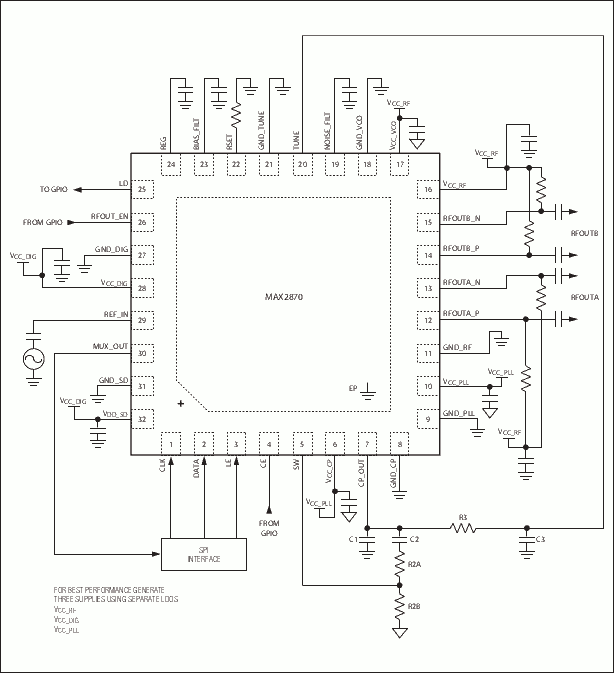
So, from my perspective: Design a small board that contains the decoupling capacitors, the in- and output matching circuitry, maybe a linear voltage regulator IC and aside from that only the loop filter, and of course a synthesizer IC. I've worked with the MAX2870 before.
It needs a reference oscillation in between 10 and 200 MHz; if you don't have something like that at hand, building a 10, 12, or 20 MHz reference oscillator out of a sub-€ quartz and an inverter isn't hard, as these crystal frequencies are abundant on the market.
The only microwave transmission line you'll need to design is the trace from chip to coax connector. That's a massive simplification over having to build everything that happens at microwave frequencies yourself.
For control, it uses SPI. Attach your favourite microcontroller, Raspberry Pi, or USB-to-SPI adapter. To know which settings to program, you don't even have to write code yourself: there's open source MAX2870 driver software, used by people that use it to control the same chip used in their commercial SDR RF frontends (schematic, p.3). So use the settings generated by that, or download Maxim's design software and let it calculate the right settings.

¹ But I'll be honest: I've etched exactly one board in my life myself. Services like OSHPark, elecrow, seeed and newly JLCPCB offer a round of PCBs manufactured and delivered to your door for < 10€ – my loss in material couldn't really keep up with that. And you actually get decent PCBs.
